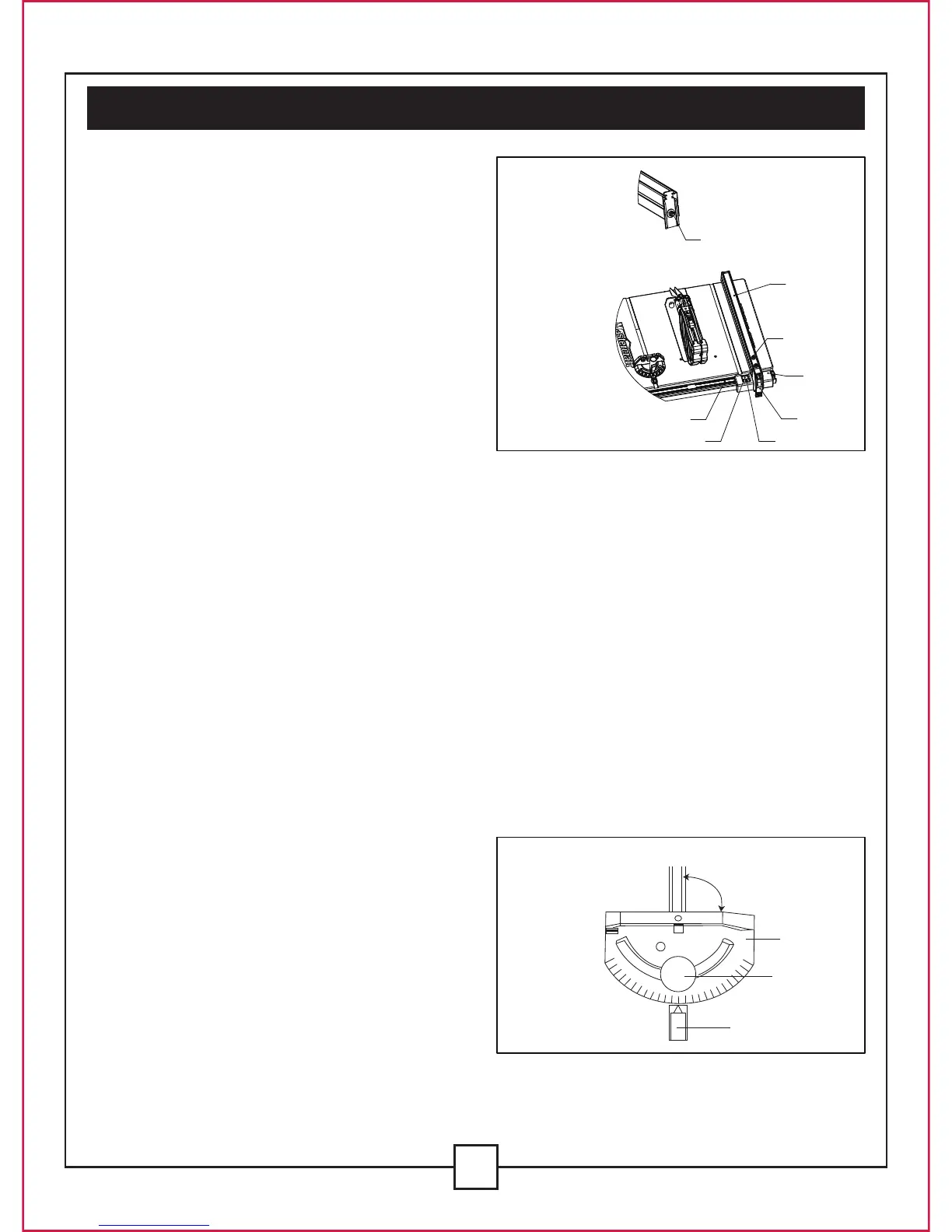
ADJUSTING THE RIP FENCE INDICATOR (FIG. 17)
1. The rip fence indicator (6) points to the measurement scale (8).The scale shows the distance
from the side of the fence closest to blade.
2. Measure the actual distance with a ruler. If there is a difference between the measurement
and the indicator, adjust the indicator (6).
3. Loosen the screw (7), and slide the indicator to the correct measurement on the scale. Tighten
the screw, and re-measure with the ruler.
V. Assembly and adjustments(continued)
18
ADJUST THE RIP FENCE (FIG. 17)
1. The fence (1) is moved by lifting the handle
(2) and sliding the fence to the desired
location. Pushing down on the handle locks
the fence in place.
2. Position the fence on the right side of the
table, along the edge of the mitre gauge
groove.
3. Lock the fence handle. The fence should
be parallel with the mitre gauge groove.
4. If adjustment is needed in order to make
the fence parallel to the groove, follow
these steps:
• Loosen the two bolts (3), and lift the handle (2).
• Hold the fence bracket (4) firmly against the front of the saw table. Move the far end of the fence
until it is parallel with the mitre gauge groove.
• Push the handle down to lock it, and tighten both screws.
5. If fence is loose when the handle is in the locked (down) position, follow these steps:
• Lift the handle (2) and turn the adjusting nut (5) clockwise until the rear clamp is snug. Do not
turn the adjusting screw more than 1/4 turn at a time.
• Over-tightening the adjusting screw could bend the rear clamping lever, which may cause the
fence to come out of alignment.
Fig. 17
ADJUST THE MITRE GAUGE (FIG. 18)
1. Loosen the lock handle (1) in order to allow
the mitre body (2) to rotate freely (Fig.18).
Position the mitre body at 90°, so that the
positive detent secures its position. Tighten
the lock handle in order to hold the mitre
body in position.
2. If the pointer (3) requires adjustment,
loosen the two screws under the pointer
using a screwdriver. Adjust the pointer to
90° on the scale, and then firmly tighten both adjusting screws.
3. To change angles on the mitre gauge, loosen the lock handle (1) and rotate the mitre body to
the desired angle, as indicated by the scale. Secure in position by tightening the lock handle.
Fig. 18
8
6
2
4
3
7
1
5
30
45
60
75
75
90
60
45
30
2
1
3
90°
 Loading...