EasyManuals Logo

Mastervolt MLI Ultra User Manual

Mastervolt MLI Ultra
32 pages
To Next Page IconTo Next Page
To Previous Page IconTo Previous Page
Page #12 background imageLoading...
Page #12 background image
12
MLI Ultra 12/1250, 24/1250 User and Installation Manual
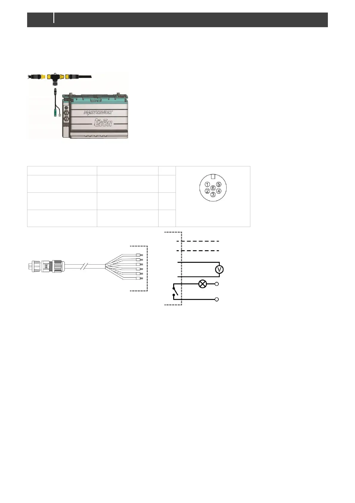
3. Connect the RJ45 CZone/MB drop cable to the black coupler on the tee and then connect to the MLI
Ultra. On the battery side, plug the connectors into either of the communication ports. LED B will
blink to confirm CZone network identification.
Figure 6: CZone drop cable
Auxiliary connector
FUNCTION
WIRE COLOR
PIN
Figure 7: connector
on the MLI Ultra
Analog SoC output
Max rating: 1mA
Green (0 10VDC)
Black (GND)
6
3
Aux. relay
Max rating: 30VDC/1A
Yellow
White
4
5
Not used
Red
Blue
1
2
Figure 8: six wire ferruled auxiliary cable
State of Charge (SoC) indication
Wire pair 3&6 can be used to monitor the SoC on external equipment, where 10V = 100% and
0V = 0%. To enable this, select the "SOC 0-10V" option in the Configuration tab, see page 15.
Auxiliary relay (dry contact)
Wire pair 4&5 can be used to control an external device like a switch, relay or lamp. This is done in
combination with a MasterBus event command or CZone circuit.
RED
BLUE
YELLOW
GREEN
BLACK
WHITE
GND
GND
VDC
0-10v
RELAY

Questions and Answers:

Question and Answer IconNeed help?

Do you have a question about the Mastervolt MLI Ultra and is the answer not in the manual?

Mastervolt MLI Ultra Specifications

General IconGeneral
BrandMastervolt
ModelMLI Ultra
CategoryCamera Accessories
LanguageEnglish

Related product manuals