MLI Ultra 12/1250, 24/1250 – User and Installation Manual
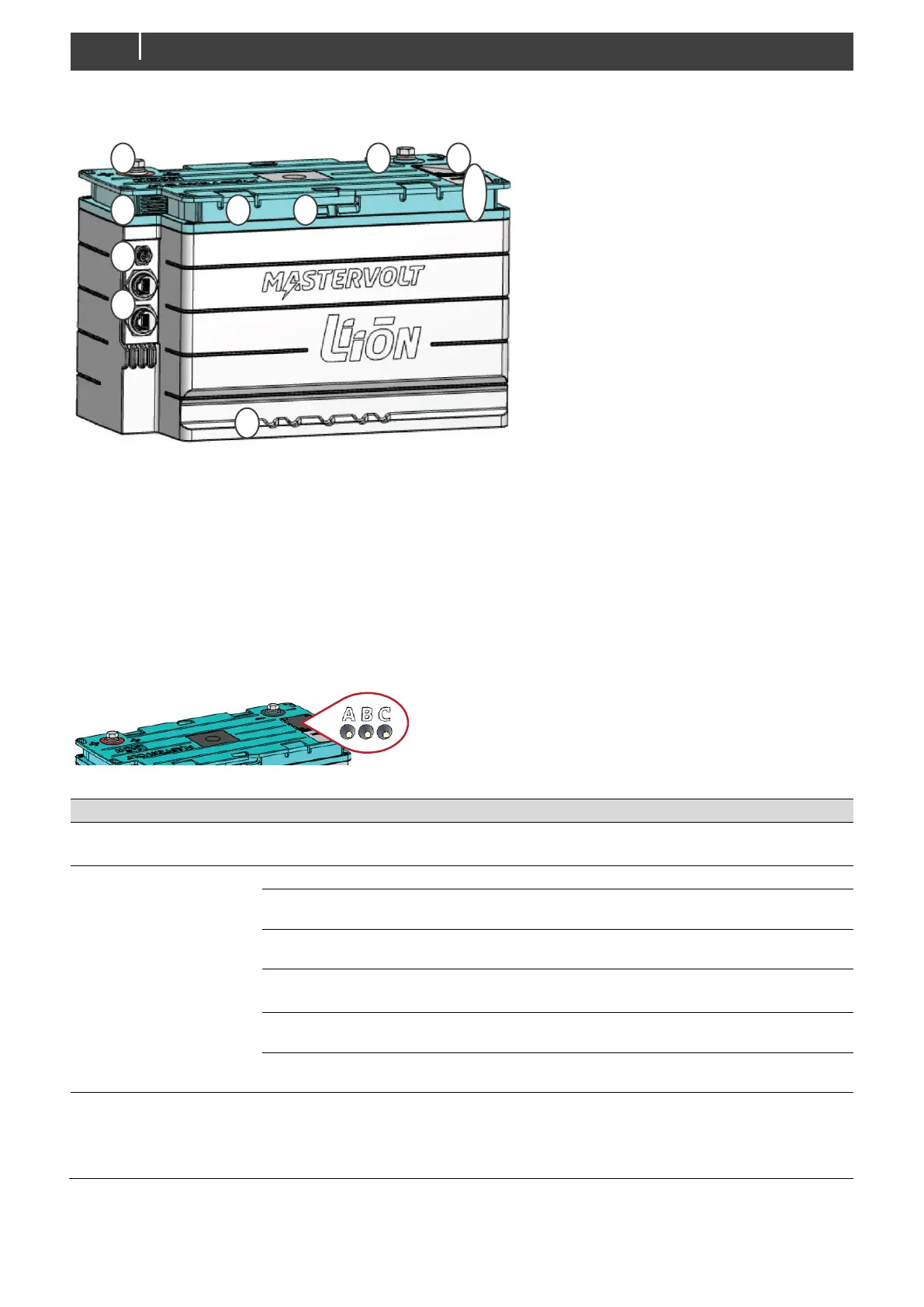
1. M8 positive terminal
2. M8 negative terminal
3. Provision for removable handle
4. Hold down edges group 31, fit battery group size 49
5. Attachment strap support
6. Protective vent; maintain adequate ventilation around this
opening. Do not touch the membrane!
7. Auxiliary connector
8. MasterBus/CZone connectors
9. Status LEDs and DIP switch
cover
10. Battery switch-button (safety
disconnect)
Figure 1: overview of the MLI Ultra 1250
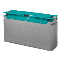
Status LEDs
Figure 2: status LEDs
If this LED is on, a BMS error has occurred or cells are damaged. Check
the installation and contact your Mastervolt dealer.
During normal operation the LED is off.
State of Charge (SoC) low. Charge the battery.
CZone network identification (during installation).
Auto cluster configuration error. See section "Using
DIP switches" on page 22.
Battery is executing a recovery procedure.
Battery is updating its firmware.
When the Battery switch-button is pressed short, this LED indicates the
status of the battery switch.
- Solid on for 1 minute: battery is on (switch is closed).
- Blinking for 1 minute: battery is off (switch is open).