PowerCombi Inverter/Charger
DC cable cross section < 6ft [2m]
Recommended wire colors (refer to local rules):
Run the cables next to each other to limit the electromagnetic field around the cables. The negative
cable should be connected directly to the negative post of the battery bank or the ground side of a
current shunt. Do not use the chassis frame as the negative conductor. The positive battery cable
must be fused and connected to the positive post of the battery bank. Use a fuse that matches the
applied wire size. The fuse with fuse-holder is available from your local Mastervolt distributor.
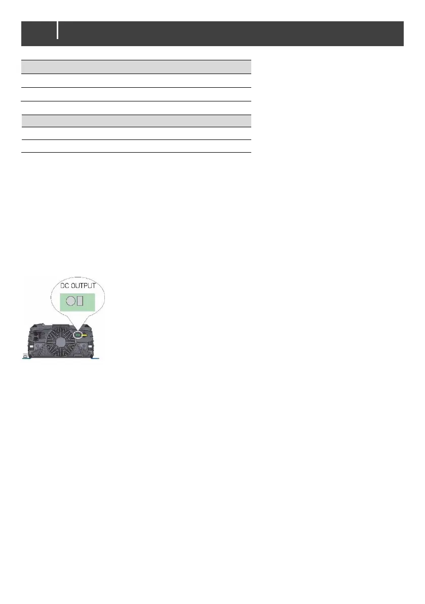
4.4.4 Auxiliary DC output wiring
The Auxiliary DC output can be used for charging a small second battery set like a starter battery.
When enabled, this output is active when external AC power is available on AC IN. The maximum
current is 20A. Use 10 to 12 AWG wire for the connection.
Step 1. Connect the negative of the 2
nd
battery to the minus of the main
battery.
Step 2. Connect the positive of the 2
nd
battery to the auxiliary DC OUTPUT of
the PowerCombi Inverter/Charger. Place a small screwdriver in the
rectangular opening and drive down to open up the clamp. Place the
wire in the round opening and remove the screwdriver.
Step 3. Integrate a 20A slow blow fuse in the plus cable.
The Auxiliary DC output fuse protects the 2
nd
battery from overcharging.
Figure 6: Auxiliary DC Ouput connector block
4.5 Things you need
Make sure you have all the parts you need to install a PowerCombi Inverter/Charger:
• PowerCombi Inverter/Charger (included).
• Optional: Battery temperature sensor with cable and plug (not included).
Note: Lithium-ion batteries require no temperature sensor as they have built-in intelligence that
monitors the internal temperature.
• DC cables to connect the PowerCombi Inverter/Charger to the batteries and common negative.
See section 4.4.3 for specifications.
• DC fuse holder with a DC fuse, to be integrated in the positive DC cable.
• Screws/bolts (Ø ¼" / 6mm) with plugs to mount the PowerCombi Inverter/Charger to a surface.
Use mounting materials which are suited to carry the weight of the PowerCombi
Inverter/Charger.
• AC cable to connect the AC input to an AC power source. See section 4.4.1 for specifications.
• Batteries. See section 4.3 for specifications.
• Appropriate and reliable cable terminals, cable lugs, battery terminals and cord end terminals.

 Loading...