Step 7. Optional: Attach the battery temperature sensor to the casing of the battery bank. Then
plug the RJ11 temperature sensor cable into the Battery Temp. sensor port (item D in
Figure 5).
Step 8. Use a small screw driver to change DIP switch settings. See section 5.1.
Step 9. Option: connect external alarm or remote switch input. See section 4.9.
Step 10. Check all wiring. If all wiring is OK: Place the inverter fuse.
Step 11. Close the connection compartment and fix the screws at the bottom.
Step 12. Switch on the PowerCombi Inverter/Charger.
Step 13. Optional: Set the desired output voltage and other configuration settings from the
PowerCombi Remote Panel or laptop/notebook connected via the MasterBus PowerCombi
Interface, see chapter 5.
4.8 PowerCombi Remote Panel (optional)
Optionally the PowerCombi Remote Panel is connected to the RJ-11remote port (REMO) on the DC
input side. Before using the PowerCombi Remote Panel, make sure the main switch is in the
Remote (═) position before startup.
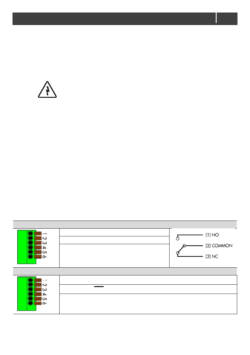
4.9 Dry contacts (optional)
The 6 pin terminal (item F in Figure 5) at the DC side offers two functions:
• Alarm output;
The alarm contact switches when a fault occurs.
• Remote switch
Install a switch for remote operation. Make sure the main switch is at Remote (═) position.

 Loading...