INSTALLATION AND COMMISSIONING
EN / SunMaster CS15TL/CS20TL / August 2010 13
6.3 INSTALLATION STEP BY STEP
See also section 4.4.
1 Fix the CS15TL/CS20TL to the wall, starting with the
mounting bracket. See figure 15. Use suitable screws
and plugs.
2 Open the communication module of the
CS15TL/CS20TL (section 4.5).
3 If applicable, connect alarm wiring and MasterBus
cables.
4 Connect the DC Solar wiring.
5 Connect the AC wiring. Refer to the manual of the AC
connectors (manual included with connector)
WARNINGS
High voltages (up to 1000 VDC) may exist on
the PV strings! Switch off the solar voltage
and verify that no dangerous voltage is
present, before starting the cable work.
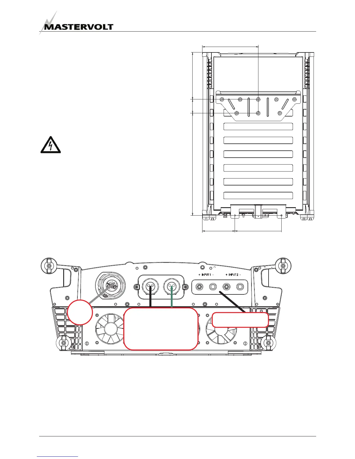
Figure 15: drilling template of bracket and housing
See figure 16.
AC connector: refer to section 6.4 AC 3-phase connector,
Communication module: refer to chapter 5,
PV input: refer to section 6.6 DC Distribution.
Figure 16: Overview of the CS15TL/CS20TL connections
AC
Communication
module
PV input
272
(10,7)
323 (12,73)
592 (23,3)
188 (7,41) 270 (10,6)
80
(3,15)