BEFORE YOU START
EN / SunMaster CS15TL/CS20TL / August 2010 9
4.5 DC CONFIGURATION
The solar or DC side of the system consists of several
photovoltaic (solar) modules, further referred to as “PV
modules”. The PV modules are connected in series to
form a so called “string”. These strings have a plus (+) and
a minus (–) connection which can be connected to the
CS15TL/CS20TL via a string combiner box, eg. the
Mastervolt StringMaster.
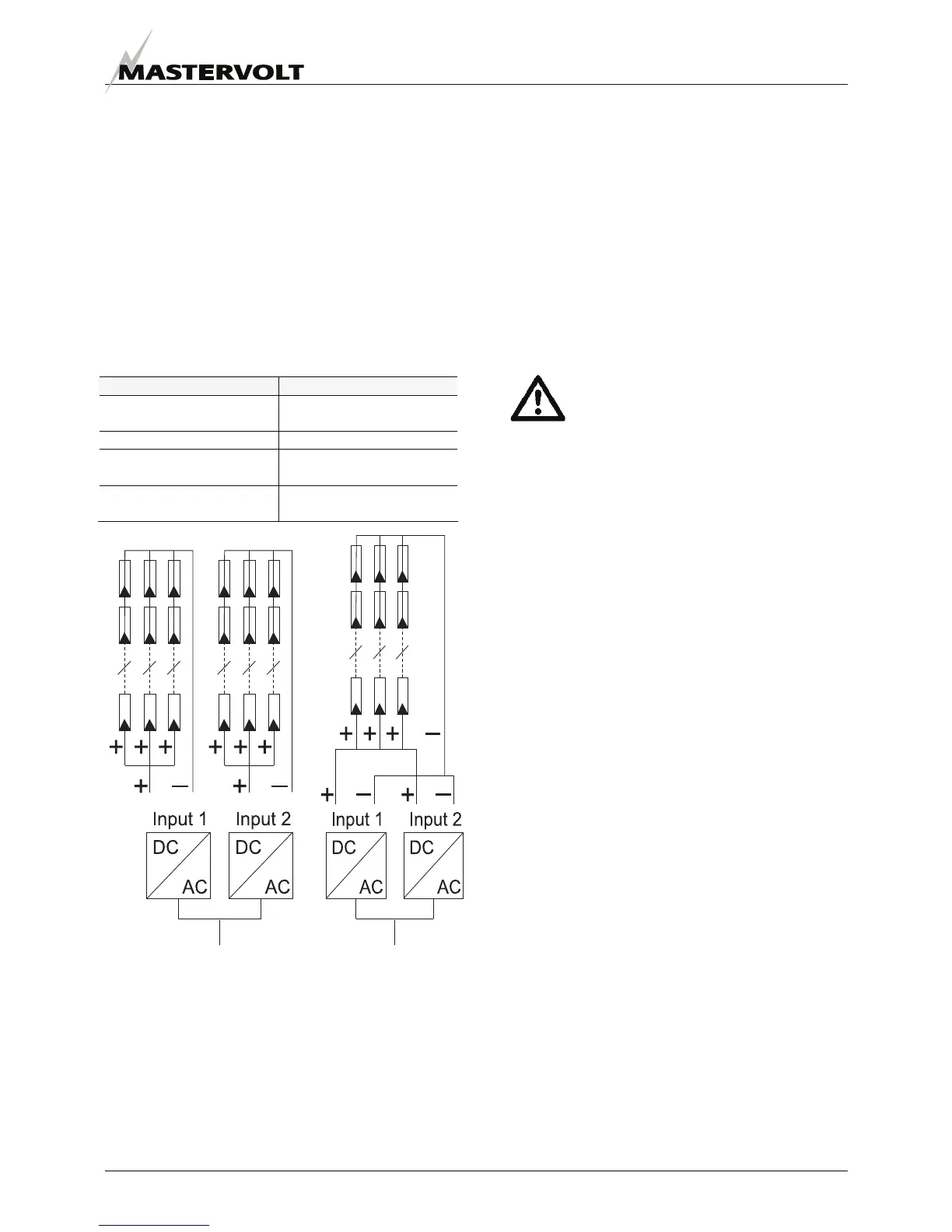
4.5.1 Separate or parallel inputs
The CS20TL has two separate inverters with an own input
each, called Input 1 and Input 2. These inputs can be used
as separate inputs (normal situation) or they can be
configured in parallel. See figures and table for the
applications.
Separate inputs Parallel operation
Per input different string
lengths possible.
For uneven numbers of
strings.
Per input max 13 kWp. MPP current above 30A.
Per input different PV
module positions possible.
For PV grounding. Refer to
section 6.5.1.
Per input different module
types possible.
Figure 5: Separate inputs and parallel operation
4.5.2 Specifications of the PV installation
The PV installation should meet next specifications:
• The maximum open circuit string voltage for each
power module at lowest possible temperature of the
PV modules may not exceed 1000V.
• Double isolated PV cabling, fitted with MultiContact
4mm type connectors must be used.
• The maximum power connected to the CS15TL may
not exceed 10 kWp per input or 19 kWp in total.
• The maximum power connected to the CS20TL may
not exceed 13 kWp per input or 25 kWp in total.
• All connection devices (wiring, terminal blocks, fuse
holders, fuses, switches etcetera) must be rated for the
applicable voltage (up to 1000V DC) and current
ratings (up to 30A DC) of the solar installation.
Do not install the CS15TL/CS20TL if the
solar-system does not comply with the
stipulations mentioned above!
4.6 DC SWITCH
For safety reasons, the use of a suitable DC siwtich is
recommended. Depending on local applicable regulations
the use of a DC switch between the PV modules and the
power modules may be mandatory. The DC switch is
included in the optional StringMaster CS 2-6 SW.
4.7 THREE PHASE AC CONFIGURATION
The CS15TL/CS20TL is intended for use in a permanent
installation, connected to a separate three phase AC
distribution group, to which no other electrical equipment is
connected. All electrical connections must comply with
local codes and regulations.
The AC output is arranged in a 400 V AC three-phase
delta configuration. Use a suitable cross section, so that
the cable loss is well below 1%. The recommended cross
section for a 10 m cable is 4,0 mm².
4.8 POWER MANAGEMENT
The CS15/20TL has a power management function built
in. It enables a grid operator to send a request for
delivering less power to the grid. For this purpose, an
optional DataControl Premium or DataControl Pro II is
connected to the inverter via RS485. The grid operator
sends his request to the datalogger that triggers the Power
Management function. In case such a request is done, the
display shows the reduction value in the home screen.
Example: ON, Pwr Mgmt 30 % means maximum 70% of
the nominal output power should be delivered. For all
power reduction values, see chapter 9. Contact your
Mastervolt supplier for more information.