INSTALLATION AND COMMISSIONING
14 August 2010 / SunMaster CS15TL/CS20TL / EN
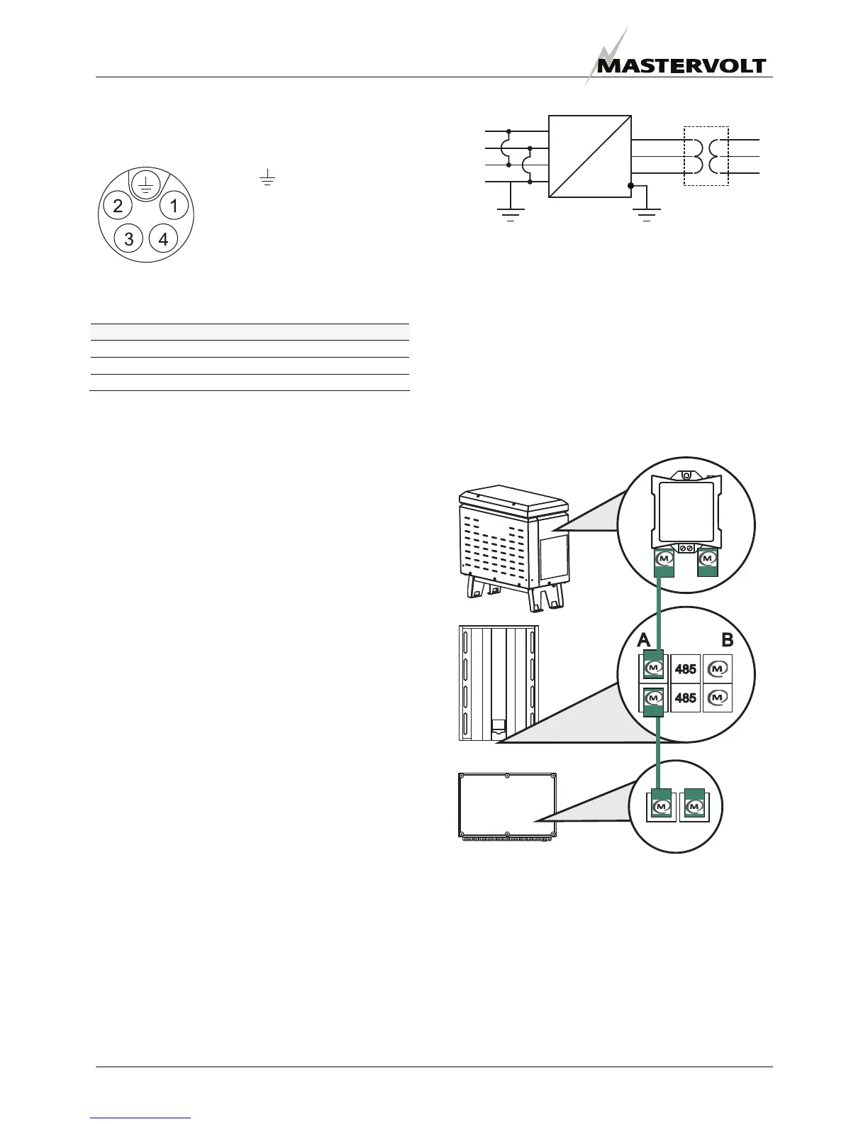
6.4 AC 3-PHASE CONNECTOR
The AC connector has five wire terminals, figure 16 shows
the connector. Connect PE first (yellow-green).
Figure 17: AC 3-phase connector
Table: minimum cable diameters for power loss under 1%.
AC cable length Diameter
<10 m 4 mm
2
10-30 m 6 mm
2
>30 m > 6 mm
2
The PE cable diameter must be at least as large as the
largest AC cable used, with a minimum of 4 mm
2
. For
more information on cable diameters, refer to the
installation norms like NEN1010. If the cable diameter
recommended exceeds the connector size, an adapter is
necessary.
6.5 ISOLATION TRANSFORMER
An isolation transformer may be necessary for two
purposes.
1. PV plant grounding (section 6.5.1);
2. Prevention of RCD tripping (section 6.5.2).
6.5.1 PV Array Grounding
Grounding of your CS20TL is necessary. This is possible
at the AC side, see figure 18. Some PV panel suppliers
prescribe connection of PE to the positive or minus DC
input. In this case, follow next steps.
• To avoid inverter damage, a high power isolation
transformer like the CS-IT20 must be installed at the
AC side.
• The DC inputs must be paralleled
• Connect the Protective Earth (PE) to the positive or
negative DC input.
• Switch off the Insulation Fault detection. See the CS-
IT20 manual for more information. Figure 18 shows the
scheme for applying the isolation transformer in your
PV plant.
Figure 18: PE at DC input isolation transformer
6.5.2 High solar array capacity
A high solar array capacitance may exist to the PV frame
or support structure (PE). The CS20TL has been designed
to withstand solar array capacities up to 4 µF. Capacities
exceeding this value may cause the internal RCD to trip,
installing an isolation transformer is necessary.
6.5.3 MasterBus connections
The CS-IT20 transformer is equipped with a MasterBus
relay for MasterBus controlled switching. Network A is
used for this purpose. Refer to figure 18 and chapter 5.
Figure 19:
MasterBus network A: CS-IT20, CS20TL, StringMaster
DC
AC
DC
AC 3-P
+
_
+
_
PE CS 20 TL CS-IT20
Protective Earth
1. Line 1 (L1)
2. Line 2 (L2)
3. Line 3 (L3)
4. Not used