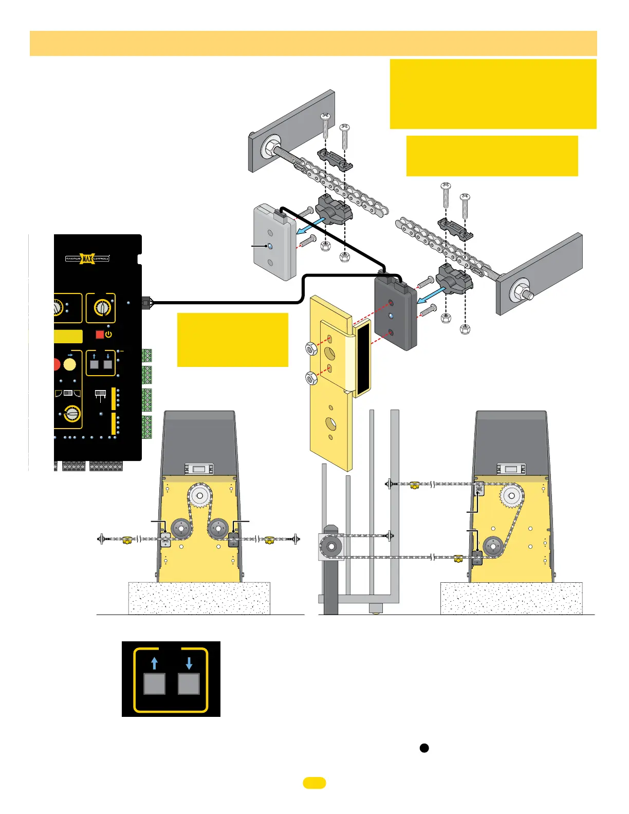
Magnet limit sensors are sold separately.
The GRAY limit sensor MUST be mounted
on the OPEN POSITION on the Back Plate on
operator. The limit sensor magnets MUST be
installed on BOTH ends of chain to indicate
the OPEN and CLOSE positions of the gate.
They will activate the corresponding LIMIT
SENSOR (Gray-Open or Black-Close) when
they move within range, stopping the gate at
the desired positions.
Limit Sensor
Magnet
Gate
Bracket
Limit Sensor
Magnet
Limit Sensor
Mounting Holes
GRAY
Limit Sensor
Gate
Bracket
IMPORTANT: LEDs MUST light up when gate
reaches OPEN and CLOSE positions or operator
WILL NOT learn gate positions. If gate positions
are not learned, gate cycling speed will remain
slow during normal operation.
IMPORTANT: Limit Sensor Magnets
MUST be installed on BOTTOM of chain
as shown.
BLACK
Limit Sensor
Plug
Plug
Install Limit Sensors:
Push and HOLD the JOG LEFT or JOG RIGHT
buttons accordingly to move the gate (release
the button to stop gate).
JOG Left/Right Buttons
Use JOG Left/Right Buttons for installation
1. Install GRAY sensor on OPEN position and BLACK sensor on CLOSE position as shown.
2. JOG gate to CLOSE position.
3. Mark magnet position on chain.
4. JOG gate open slightly and install magnet.
5. JOG gate to OPEN position.
6. Mark magnet position on chain.
7. JOG gate closed slightly and install magnet.
8. Gate positions can now be learned, see .
Plug
OPEN
JOG
LEFT RIGHT
optional magnet limit sensors
CLOSING
CLOSINGOPENING
RD
OTOR
ER
AD
ERD
MOTOR
OVER
LOAD
MAX
OFF
MAX
SENSE
BATTERY
BACKUP MODE
SENSITIVITY
MOTION CONTROL
OPEN
GATE SPEED
MAG
LOCK
UL
ENTRAP
PRIMARY/
SECONDARY
LINK
STOP CLOSE
MOTOR
INPUTS
CLOSE
TIMER
MAGLOCK
DELAY
JOG
CE
RY
LEAVE
CLOSED
LEAVE
OPEN
OPEN
1 TIME
LINK
OK
MOTOR
POSITION
INPUTS
SLIDER
LIMIT
SWING
LIMIT
GND
OPEN ONLY NC
OPEN ONLY 10K
PHOTO CLS NC
OPEN/CLS NC
GND
12VDC OUT
GND
GND
GND
GND
GND
JOG RIGHT
JOG LEFT
TAMPER IN
TAMPER NO
GATE DISABLE
MANUAL RELEASE
GND
(-)
(+)
CLOSE
COM
COM
STOP
OPEN
CLS ONLY 10K
OPEN/CLS 10K
12VDC OUT
NO
COM
NC
LEFT
ON/OFF
BATTERY
RIGHT
QUICK
CLOSE
OPEN
LEFT
OPEN
RIGHT
GATE
FF
MIN MIN
AX MAX
ON
OFF 2.5 sec
1.5 sec
MATRIX III
3
1
14
16
MIN
12
9
7
UL SENSOR N.C.UL SENSOR 10K
GATE OPEN
COM
GATE CLOSED
MIN
MATRIX III
SWING / SLIDE
Rear Mounting PositionFront Mounting Position
Back
View
Back
Plate
Back
Plate
Back
View
Limit Sensor
Magnet
GRAY Open Position
GRAY Open Position
Black Close Position
Black Close Position
Limit Sensor
Magnet
Limit Sensor
Magnet
Limit Sensor
Magnet
IMPORTANT:
Gray Limit sensor MUST
be in the OPEN position
on the operator.
CLOSE
LED lights when
sensing a limit
sensor magnet.
L
I
M
I
T
S
E
N
S
O
R
Back Plate
7
Limit Sensor
Matrix III Connection
28
UL 325 2018 Standard - MAX 1500 PRO/2200 PRO/F18 PRO Matrix III Instal
l Version 7a