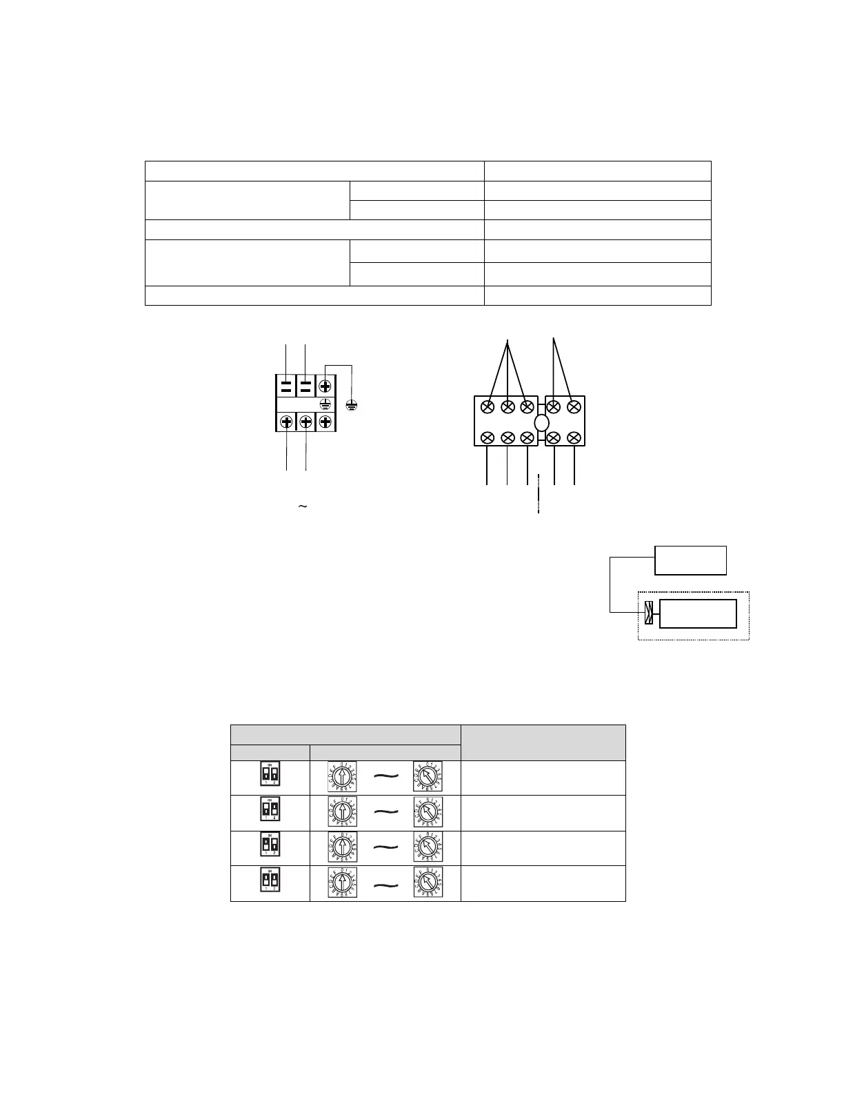
8.7.1 Terminal Board Diagram
Please refer to the indoor unit wiring diagram for the wiring.
NOTE: The air-conditioners can connect with Central Control Monitor (CCM). Before operation, please wiring correctly and
set system address and network address of indoor units.
■ Power supply specifications
Power supply
Indoor unit power wiring (mm²)
Below 20m
Twisted pairwire 2.5 mm²
Below 50m Twisted pairwire 6 mm²
The power cord type designation is H05RN-F or above.
INDOOR UNIT PO
WER
2
20-
240
V
~
50Hz
XT1
Y/G
DE
R
KCALB
L N
DE
R
KCALB
DE
R
KCAL
B
ETIHW
KCALB
EU
LB
1 2
X
Y
E
DER
TO Timer
To Central Control Monitor
(CCM)COMM. BUS
XT3
DER
- Please adopt the shielded twisted-pair wire, and connect the shielded layer to E.
The reserved wire control function is indicated in broken line table, users can
purchase the wire controller when necessary.
WIRE CONTROLLER
T
o wi
re co
ntr
ol
le
r
DISPLAY BOARD
8.7.2 Network address setting
Every air-conditioner in network has only one network address to distinguish each other. Address code of air-conditioner in
LAN is set by code switch on Network Interface Module (NIM), and the set range is 0-63.
Network address code
00 ~ 15
16 ~ 31
32 ~ 47
48 ~ 63
38