INSTALLATION PROCEDURES
3-1
SECTION 3
INSTALLATION PROCEDURES
3.1 DIMENSIONL CLEARANCES
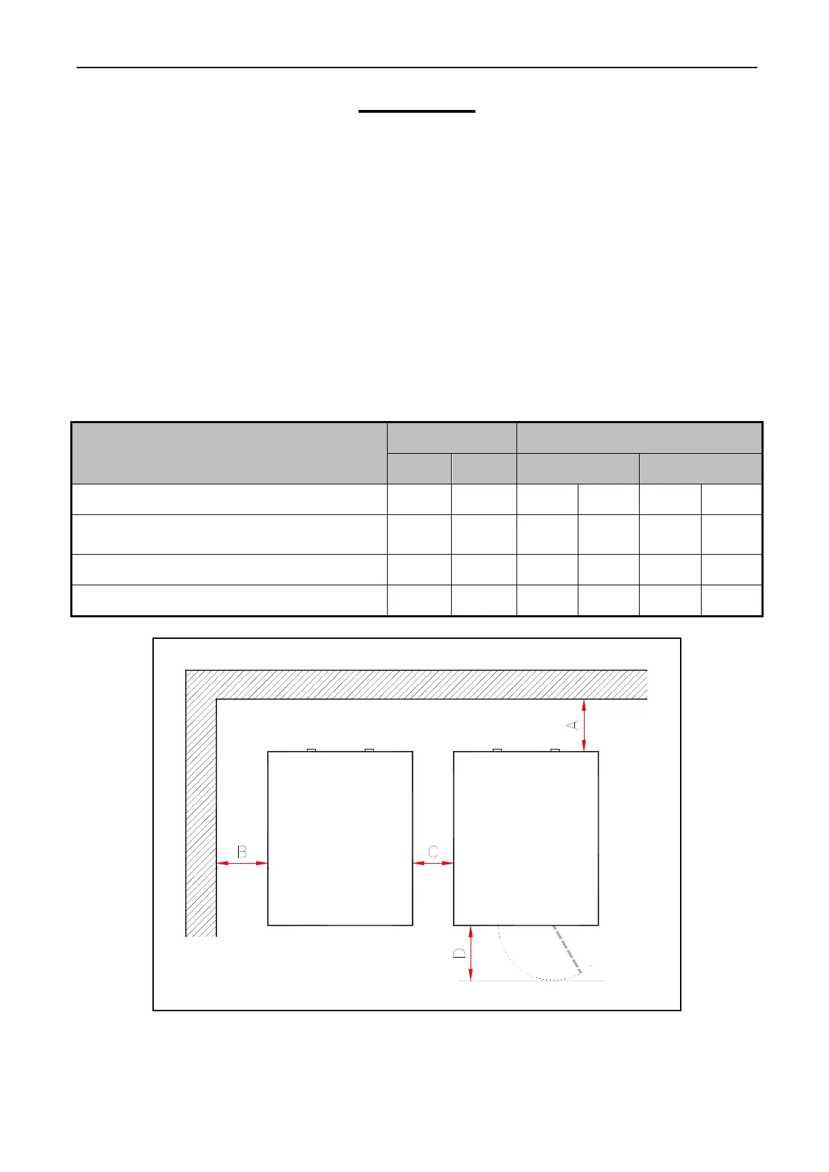
When installing the washer – extractor, it is important to allow adequate clearance on all
sides of the machine. When multiple machines are installed, it is important to allow for the specified
minimum clearances between machines. The following Table 3-1 shows recommended minimum
clearances for the various freestanding models.
NOTE: The dimensions are approximate and subject to normal manufacturing tolerances.
If exact dimensions are required for construction purposes, request certified
drawings from the factory. We reserve the right to make changes at any time
without notice.
Table 3-1 Minimum service clearances
Detail
Unit HARDMOUNT Series
Metric US Recommended Minimum
(A) Minimum rear clearance mm. inch 760 30 305 12
(B) Minimum clearance between machine
and wall
mm. inch 455 18 25 1
(C) Minimum clearance between machines mm. inch 455 18 25 1
(D) Minimum font clearance mm. inch 838 33 838 33
Fig. 3-1 Dimensions for construction