INSTALLATION PROCEDURES
3-8
For personal safety and for proper operation, the machine must be grounded in accordance
with state and local codes and in the USA in accordance with the National Electric Code, article
250 – 96.
The ground connection must be to a proven earth ground, not to conduit or water pipes.
Do not connect the system is used, the neutral (N) leg at the terminal strip.
If a DELTA supply system is used, the high leg may be connected to L1, L2 or L3, as the
machines are equipped with control transformer.
Insure that the control transformer taps are connected in accordance with the incoming line
voltage. Verify connections as shown on the schematic with each machine.
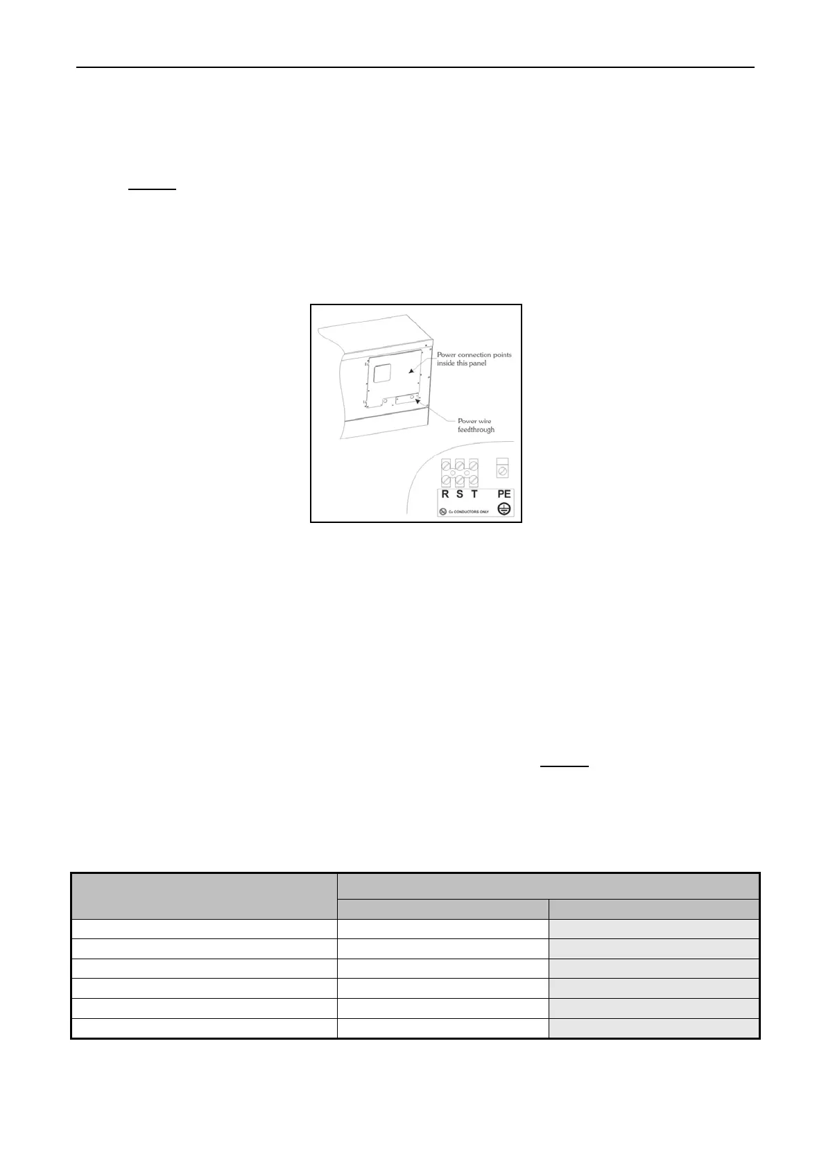
Fig. 3-7 Electrical Service Connection Detail
3.6 WATER CONNECTION
Individual hot and cold plumbing lines with individual shut – off valves must be available to
the machine. Hot water should be minimum of 160 °F (70 °C). If lower temperature water is used
the machine should be equipped for steam heating to heat the wash solution to desired temperature.
Best performance will be realized if water is provided at a pressure of 30 – 87 psi (2 – 6 Bar).
Although the machine will function properly at lower pressures, increased fill times will occur.
Flush the water system for at least two minutes prior or initial use.
Use flexible hoses and install separate screen filters in the lines to keep rust and other foreign
particles out of the solenoid valves. Hang the hoses in a large loop. Do not allow the hoses to link.
The water connections to the machine should be supplied by a hot and cold water line of least the
sizes shown in the table below. Installation of additional machines will require proportional larger
water lines.
Table 3-5 Water connection detail
NUMBER OF MACHINES
Pipe Size for HARDMOUNT Series
To avoid eventual water hammer in the water line, suitable devices to reduce the water
hammer should be installed.