INSTALLATION PROCEDURES
3-5
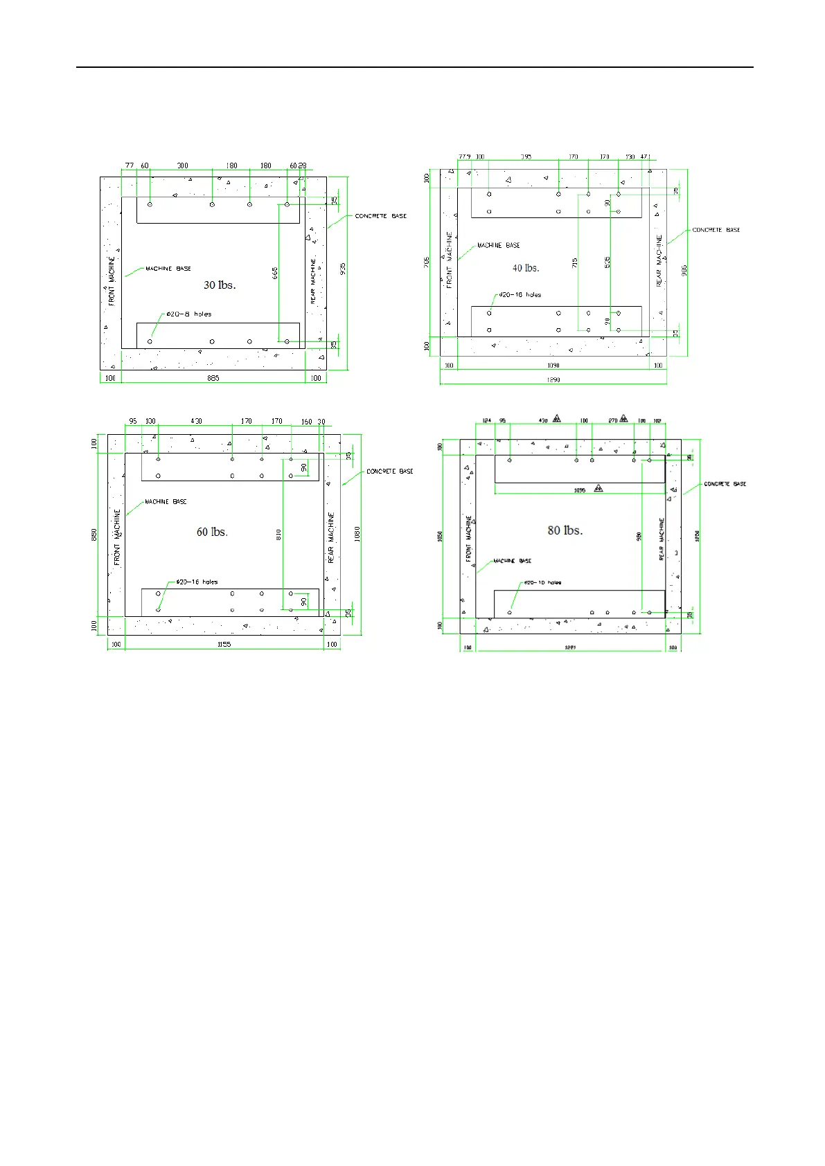
3.3.1 MACHINE BASE MOUNTING HOLE CONFIGURATION
Below are the standard hole configurations for the HARDMOUNT Series mounting.
Fig. 3-5 Bolt hole layout
3.4 DRAIN CONNECTION
A drain system of adequate capacity is essential to the machine performance. Ideally the
water should empty through a 4 inch vented pipe directly into a sump or floor drain. See figure 3-6.
• A flexible connection must be made to a vented drain system to prevent an airlock or
siphon effect. If proper drain size is not available or practical, a surge tank is required. A
surge tank in conjunction with a sump pump should be used when gravity drainage is not
possible, such as in below – ground – level installations.
• Before any deviation from specified installation procedures is attempted, the customer or
installer should contact the manufacturer. Increasing the drain hose length, installing
elbows, or causing bends will decrease drain flow rate and increase drain time, impairing
machine performance. If the drain arrangement is inadequate, the machine will not
extract and will not discharge water properly.