INSTALLATION PROCEDURES
3-10
3.8.1 CHEMICAL CONNECTION
The supply compartment on the HARDMOUNT Series is located on the front of the
machine. Supply cups can be accessed by opening the dispenser lid. The supply cups can be
removed and filled as desired. Supply compartments are numbered 1, 2, 3 and 4 from the right of the
machine to the left.
Each cup supply will flush when Detergent is programmed in the control. The programmed
chemical signal also appears as a 24VAC signal at the external chemical terminal strip for the
duration of each programmed signal.
External supply connections for the HARDMOUNT Series washer – extractors are located
on rear of the machine at the vacuum breaker. Hose connections should be made via the threaded
connectors. See figure 3-9.
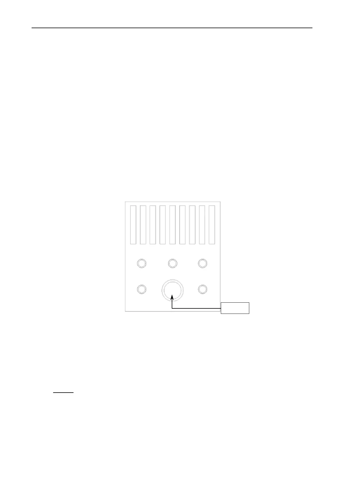
1. Remove plugs from base.
2. Install the supplied chemical nipple, using Teflon tape.
3. Insert tubes onto the nipples, using small hose clamps or wire ties to prevent the hose from
slipping off.
For the plastic supply box, you must drill the nipples prior to use (max 1/4” bit). A 1/2 NPT
connection is also provided for flushing systems.
Fig. 3-9 Plastic Vacuum Breakers / Supply Box
3.8.2 CHEMICAL SIGNAL CONNECTIONS
Connection terminals are located in the rear control box for output signals to the chemicals
injection supply pump.
Terminals SUPPLY 1 through SUPPLY 4 provide signals for external chemical supply
pumps. The signal is a maximum of 0.5 amps at 24V 50/60Hz.
Do not attempt to increase circuit breaker rating as this will cause damage to the washer –
extractor circuitry and void the warranty.
Any injection system pump, which requires 24 – 220 V.AC, must be powered by a separate
external power source.