INSTALLATION PROCEDURES
3-7
Never touch terminals or components of theca AC drive unless power is
disconnected and the “CHARGE” indicator LED is off. The AC drive retains
potential deadly voltage for some time after the power is disconnected. There is
no user –
serviceable parts inside the AC drive. Tampering with the drive will
void the warranty.
Dangerous voltages are present in the electrical control boxes and at the motor
terminals. Only qualified personnel familiar with electrical test procedures test
equipment, and safety precautions should attempt
troubleshooting. Disconnect power from form the machine before removing the
control box cover, and before attempting any service procedures.
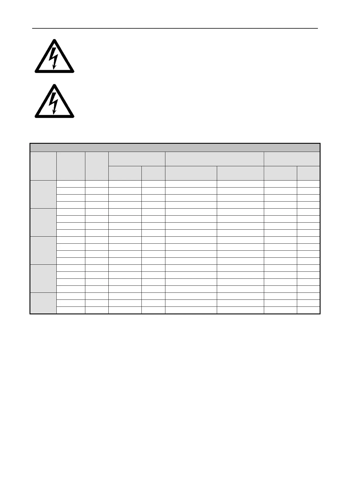
Table 3-4 Electrical Service Requirements
Model Voltage Phase
Wire Size
Elec. Hot water, Steam Elec.
Elec.
20 lbs.
30 lbs.
40 lbs.
60 lbs.
80 lbs.
NOTE: For single phase (1Ø) operation, connect input power to L1 and L2, leaving the L3
terminal open.
NOTE: Wire sizes shown are for copper, THHN, 90 conductor per NEC article 310 (USA).
The machine should be connected to an individual branch circuit not shared with lighting or
other equipment because this is a vibrating machine, the use of SO cable or similar, with a twist –
lock plug, to connect the machine to main power is recommended. A shielded liquid tight or
approved flexible conduit with proper conductor of correct size installed in accordance with National
Electric Code (USA) or other applicable codes is also acceptable. The connection must be made by
a qualified electrician using the wiring diagram provided with the machine. See the electrical
connection data chart for correct wire sizes.
Use wire sizes indicated in the chart for runs up to 50 feet (15 m). Use next larger size for
runs of 50 to 100 feet (15 – 30 m). Use 2 sizes larger for runs greater than 100 feet (30 m).