XStream™OEMRFModule–ProductManualv5.x00[2006.02.24]
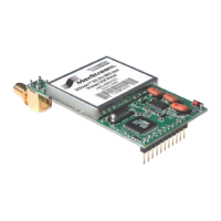
MaxStream RS-232/485 Interface Board
B-01a. Power Switch
FigureB‐01. FrontView
©2006MaxStream,Inc.ConfidentialandProprietary 53
B-01b. LEDs
The LED indicators visualize diagnostic status information. The
module’s status is represented as follows:
erial Data Out (to host)
m) = Power/TX Indicator (Red light is on when
riefly during RF transmission)
Yellow (top LED) = S
Green (middle) = Serial Data In (from host)
Red (botto
powered, off b
B-01c. Serial Port
Standard female DB-9 (RS-232) DCE connector – T nnector
-422 connectio
his co
can be also used for RS-485 and RS ns.
B-01d. Power Connector
7-18 VDC Power Connector (Center positive, 5.5/2.1mm) – Power
B-9 Serial Port.
can also be supplied through Pin 9 of the D
B-02a. DIP Switch
FigureB‐02. BackView
ot b ime
the module assembly is powered-on, the processor must be
disabled by populating J7 on the interface board.
B-02b. Config (Configuration) Switch
NOTE: In cases where AT Commands should n e sent each t
The Configuration Switch provides an alternate way to enter “AT
Command Mode”. To enter “AT Command Mode” at the module’s
default baud rate, hold the Configura
tion Switch down while
powering on the module using the Power Switch [B-01a].
FigureB‐03. MaxStreamXIB
Move the Power Switch to the on (up) position to power the
Interface Board. DIP Switch [B.2a] settings are only read
during a power-up sequence.
‐R(RS‐232/485)InterfaceBoardDIPSwitchSettings
The DIP Switch automatically configures the XStrea
e the module
ow
ms the module
e
m OEM RF
Module to operate in different modes. Each tim
assembly (interface board + the RF Module) is p
ered-on,
intelligence on the XIB-R interface board progra
according to the positions of the DIP Switch. [Se
figure below
for DIP Switch settings]
Refertotableinthe
AutomaticDIPSwitch
Configurationssection[next
page]formoreinformation
regardingconfigurations
triggeredbytheDIPSwitch.
DIPSwitch
Config
B‐01a.
Power
Switch
B‐01b.
LEDs
SerialPort
wer
B‐01c.
B‐0d.
B‐02a.
B‐02b.
Switch
Po
Connector
Downloaded from Elcodis.com electronic components distributor
 Loading...