XStream™OEMRFModule–ProductManualv5.x00[2006.02.24]
RS-485 (4-wire) & RS-422 Operation
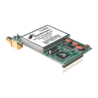
DIP Switch Settings and Serial Port Connections
FigureB‐17FigureB‐18
RS‐485(4‐wire)andRS‐422PinsusedonthefemaleRS‐232(DB‐9)
DIPSwitchSettingsSerialConnector
©2006MaxStream,Inc.ConfidentialandProprietary 60
FigureB‐19
RS‐485(4‐wire)&RS‐422withTermination(o
ptional)
TableB‐07. RS‐485/422(4‐wire)SignalsandtheirimplementationswiththeModuleAssembly
Termination is the 120 Ω resistor between T+ and T-.
DIP Switch settings are read and applied only while powering-on.
DB-9 Pin
RS-485/422
Name
Description Implementation
2 T- (TA)
Transmit Negative
Serial data sent from the XStream Module Assembly
Data Line
3 R-
Receive Negative
Serial data received by the XStream Module Assembly (RA)
Data Line
5 GND Signal Ground Ground
7 R+ (RB) Serial data rec Assembly
Receive Positive
Data Line
eived by the XStream Module
8 T+ (TB)
Transmit Positive
Serial dat mbly
Data Line
a sent from the XStream Module Asse
9 PWR Power
O
ptional power input that is connected internally
to
the front power connector
1, 4, 6 not used
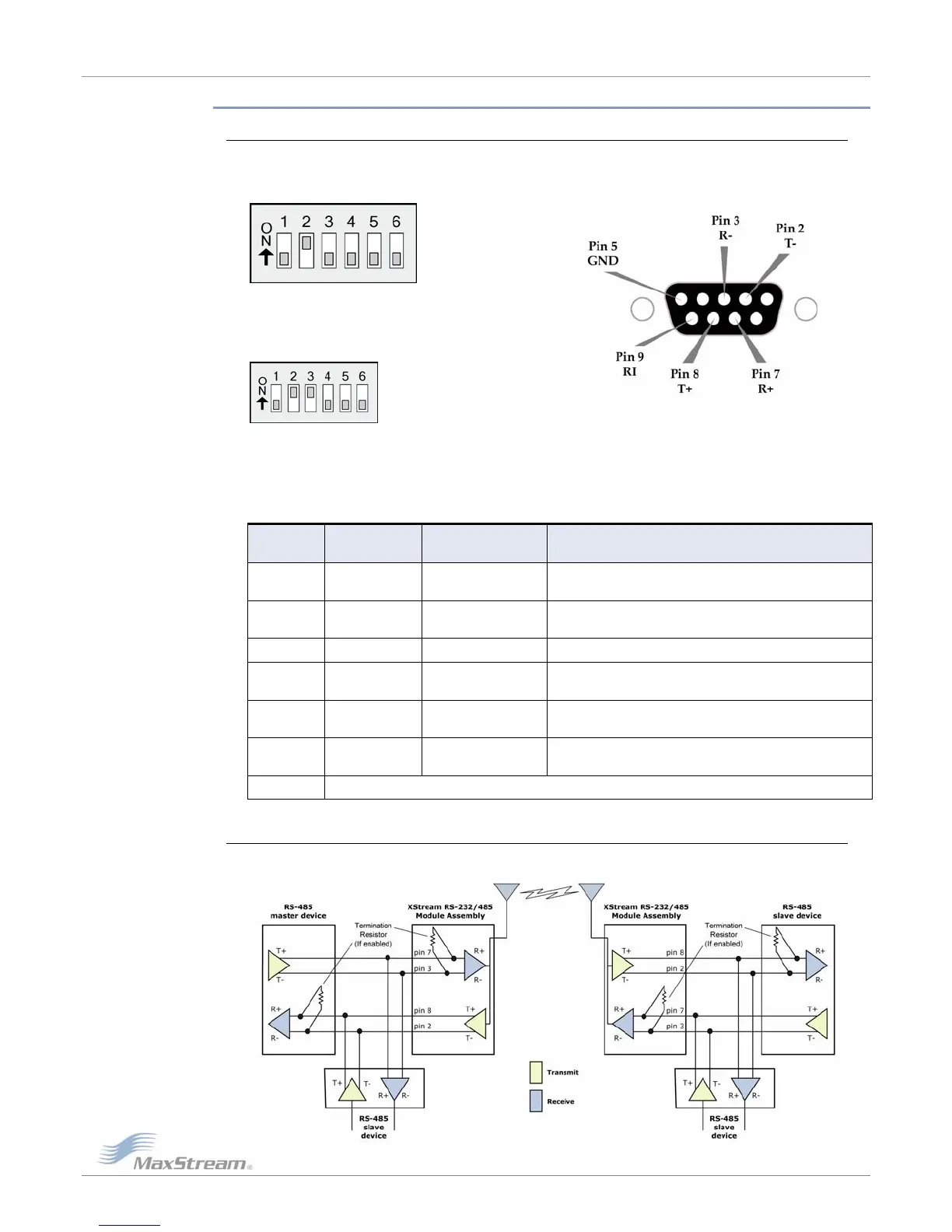
Wiring Diagram: RS-485 (4-wire) Half-Duplex
FigureB‐20.XStreamModuleAssemblyinanRS‐485(4‐wire)environment
Downloaded from Elcodis.com electronic components distributor
 Loading...