XStream™OEMRFModule–ProductManualv5.x00[2006.02.24]
RS-485 (2-wire) Operation
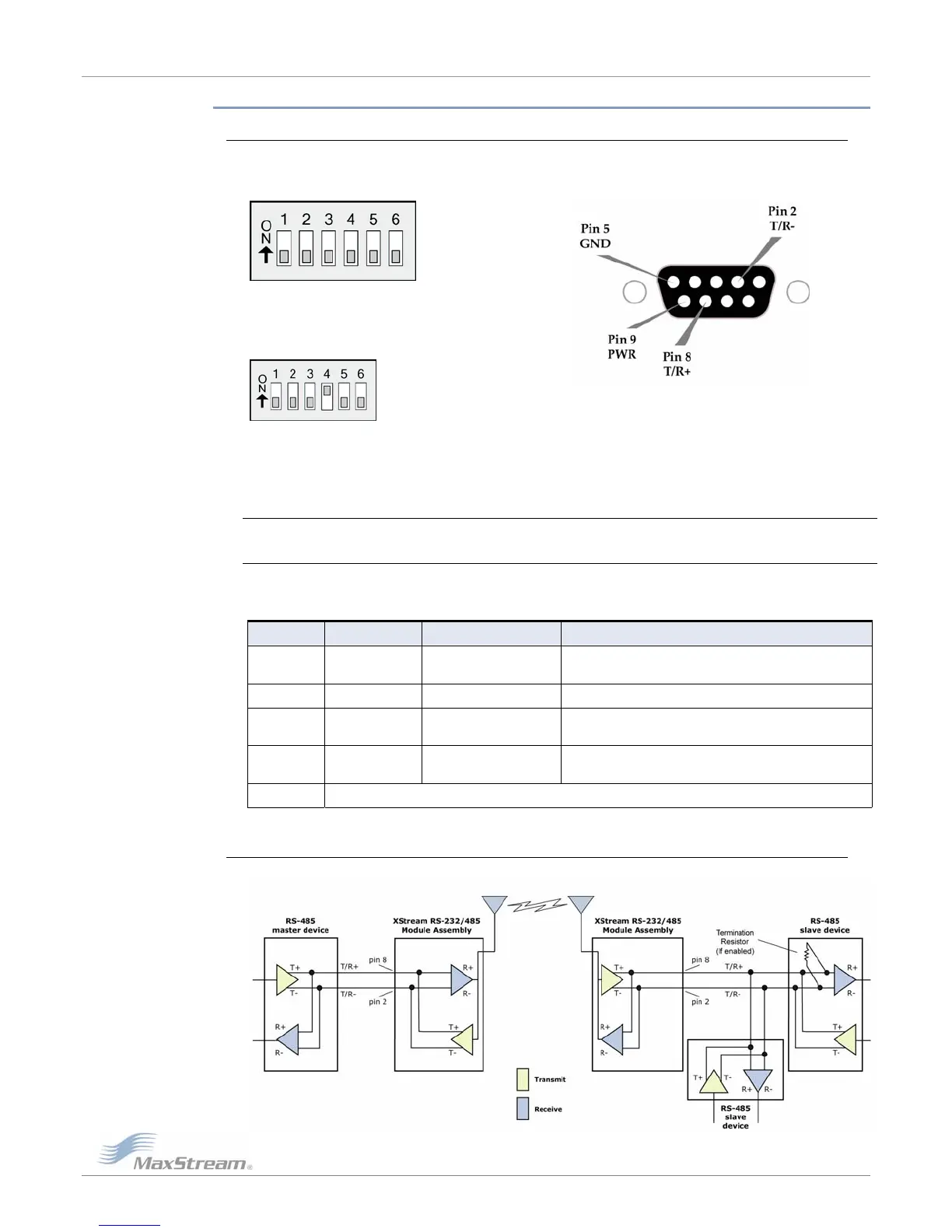
DI Switch Settings and Serial Port Connections P
F
RS
igureB‐13.FigureB‐14.
‐485(2‐wire)Half‐DuplexPinsusedonthefemaleRS‐232(DB‐9)
IPSwitchSettingsSerialConnector
igureB‐15
‐485(2‐wire)withTermination(optional)
rmination is the 120 Ω resistor between T+ and T-.
itch settings are read and applied only while powering-on.
r pin designations used in
D
©2006MaxStream,Inc.ConfidentialandProprietary 59
F
RS
Te
DIP Sw
Note: Refer to Figure B-022. & Figure B-023 [p45] for RJ-45 connecto
RS-485/422 environments.
TableB‐06. RS‐485(2‐wirehalf‐duplex)SignalsandtheirimplementationsontheXStreamModule
Assembly
DB-9 Pin RS-485 Name Description Implementation
2 T/R- (TRA) Negative Data Line
Transmit serial data to and from the
XStream Module Assembly
5 GND Ground Signal Ground
8 T/R+ (TRB) Positive Data Line
Transmit serial data to and from the
XStream Module Assembly
9 PWR Power
Optional power input that is connected internally
to the front power connector
1, 3, 4, 6, 7 not used
Wi ing Diagram: RS-485 (2-wire) Half-Duplex r
Figure
B‐16.XStreamModuleAssemblyinanRS‐485(2‐wire)half‐duplexenvironment
Downloaded from Elcodis.com electronic components distributor
 Loading...