XStream™OEMRFModule–ProductManualv5.x00[2006.02.24]
1.5. Electrical Characteristics
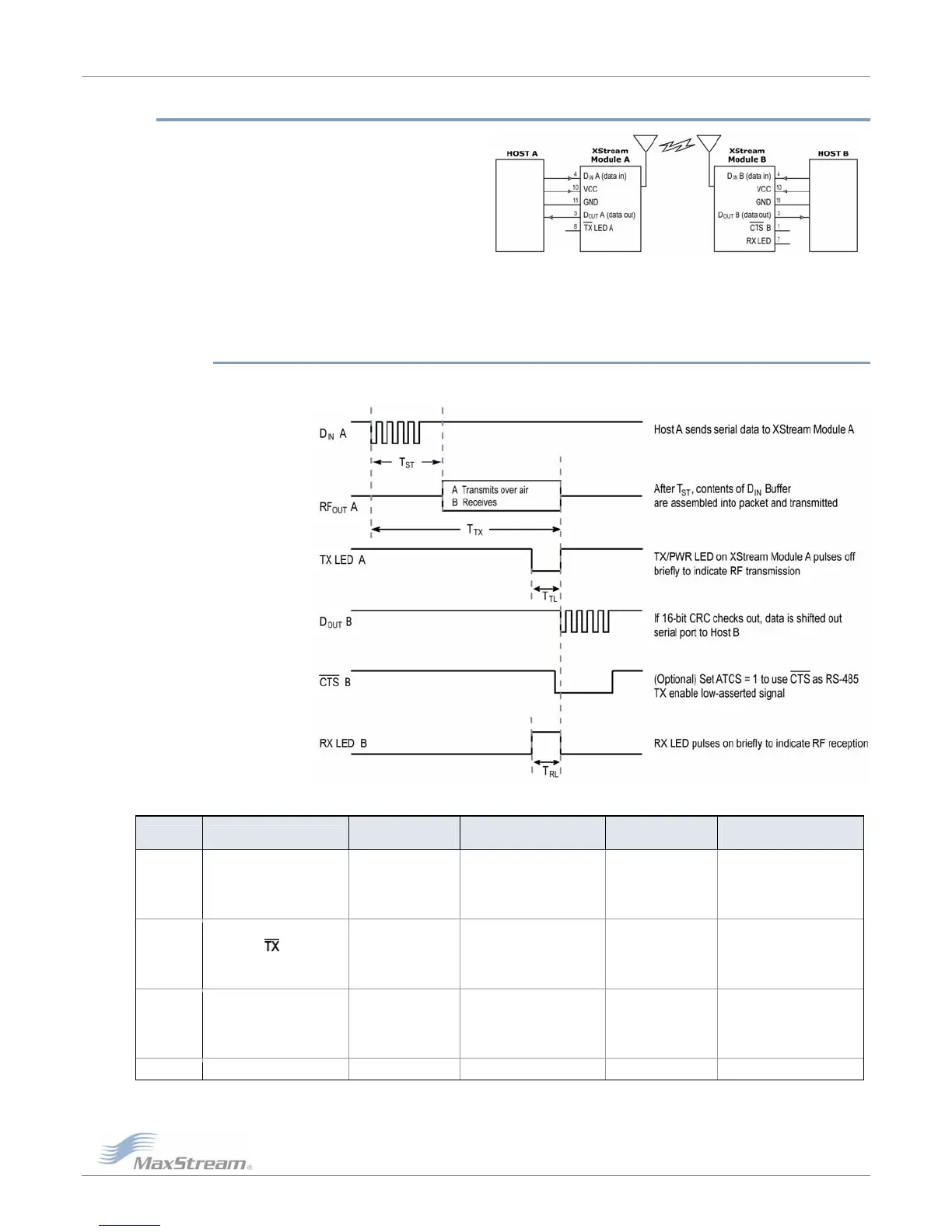
Figure1‐03. SystemBlockDiagram
Basicwirelesslinkbetweenhosts
The data flow sequence is initiated when the first byte of data is received in the DI Buffer of the
transmitting module (XStream Module A). As long as XStream Module A is not already receiving
RF data, data in the DI Buffer is packetized, then transmitted over-the-air to XStream Module B-0
1.5.1. Timing Specifications
Figure1‐04. TimingSpecifications(“A”and“B”refertoFigure1‐03.)
Table1‐04. ACCharacteristics(SYparameter=0,symbolscorrespondto
Figure1‐03andFigure1‐04.)
Symbol Description
19200 baud rate
(32 byte packet)
19200 timing
(B=number of bytes)
9600 baud rate
(32 byte packet)
9600 timing
(B=number of bytes)
T
TX
Latency from the time data is
transmitted until received
54.0 ms
For 0 < B < 64,
T = 41.6 + (0.4 * B) ms
For B > 63,
T = 66.8 ms
72.0 ms
For 0 < B < 40,
T = 46.27 + (0.73 * B) ms
For B >= 39 bytes,
T = 74.80 ms
T
TL
Time that
/PWR pin is
driven low
8.4 ms
For 0 < B < 14,
T = 3.24 + (0.4 * B) ms
For B > 13,
T = 8.48 ms
16.8 ms
For 0 < B < 14,
T = 6.50 + (0.8 * B) ms
For B > 13,
T = 16.80 ms
T
RL
Time that RX LED pin is
driven high
13.6 ms
For 0 < B < 65,
T = 0.79 + (0.408 * B)
For B > 64,
T = 26.9 ms
25.6 ms
For 0 < B < 37,
T = 1.63 + (0.794 * B)
For B > 36,
T = 30.2 ms
T
ST
Channel Initialization Time 35.0 ms 35.0 ms 35.0 ms 35.0 ms
©2006MaxStream,Inc.ConfidentialandProprietary 7
Downloaded from Elcodis.com electronic components distributor
 Loading...