XStream™OEMRFModule–ProductManualv5.x00[2006.02.24]
Interfacing Protocols
The Module Assembly supports the following interfacing protocols:
2
RS-2
• RS-232
• RS-485 (2-wire) Half-Duplex
• RS-485 (4-wire) and RS-42
32 Operation
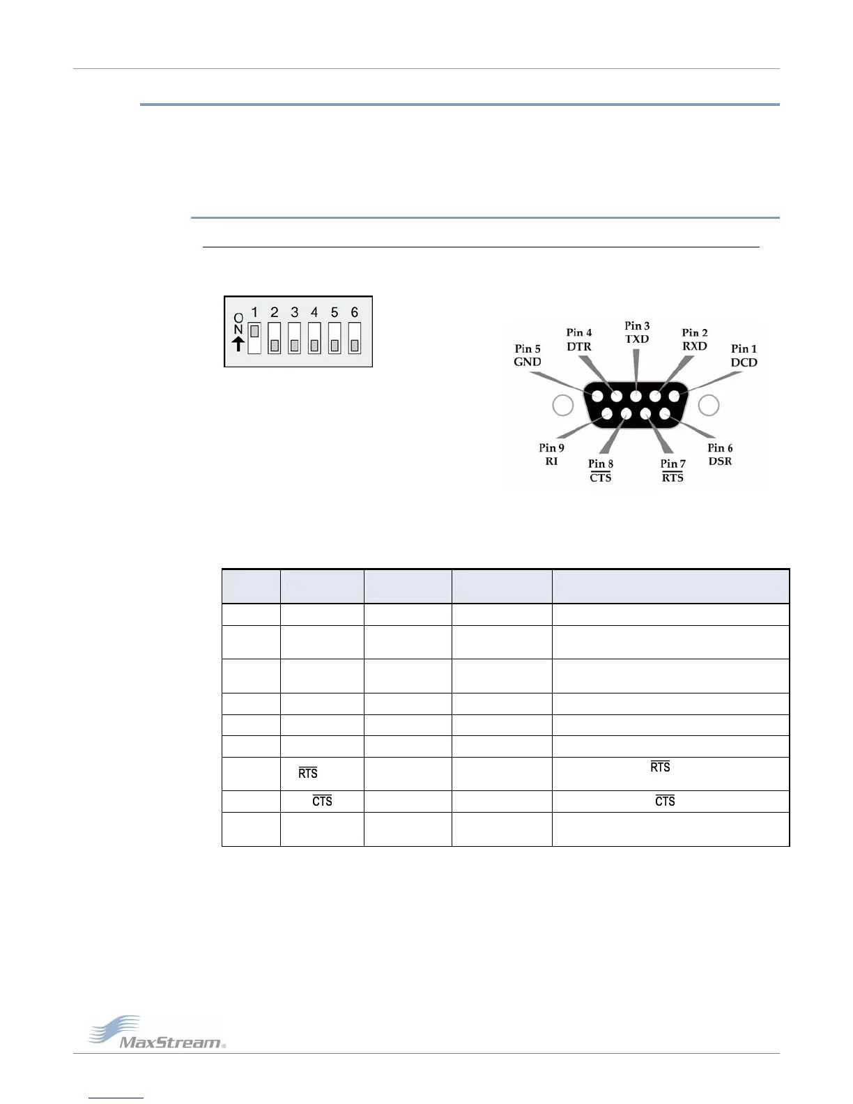
DIP Swi al Port Connections tch Settings and Seri
FigureB‐08.FigureB‐09
settingsarereadandapplied
ModuleAssembly
ontallineoverpinname.)
RS‐232DIPSwitchSettingsPinsusedonthefemaleRS‐232(DB‐9)
SerialConnector
DIPSwitch
onlywhilepowering‐on.
TableB‐05. RS‐232SignalsandtheirimplementationsontheXStream
(Low‐assertedsignalsaredistinguishedbyhoriz
AT Command
DB-9 Pin RS-232 Name Description Implementation
Reference*
1 DCD DO3 Data-Carrier-Detect Connected to DSR (pin6)
2 RXD DO Received Data
Serial data exiting
the Module Assembly (to host)
3 TXD DI Transmitted Data
Serial data entering
into the Modul
e Assembly (from host)
4 DTR DI3 Data-Terminal-Ready Can enable POWER-DOWN on the Module Assembly
5 G Groun Ground ND - d Signal
6 DSR Data-Set-Rea ConnectedDO3 dy to DCD (pin1)
7
©2006MaxStream,Inc.ConfidentialandProprietary 57
/ CMD Request-to-S
Provides
flow control or
Mode” on the Mo
enab
DI2 end
les “Command dule
8 DO2 Clear-to-Se Provides nd flow control
9 DI Ring Indicato
ower input that o the
tive lead of the ctor
- r
posi
Optional p is connected internally t
front power conne
*Th ommandReference asassociativetagwhe commands
odule.“DI”standsforDataInputand“DO”forDataOutput.
eATC provides nusingtheAT toprogramthe
M
Downloaded from Elcodis.com electronic components distributor
 Loading...