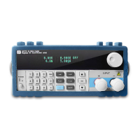
Diagram 3.2 Front panel
① The upper half is the black Vacuum Fluorescent Display (VFD) display screen.
② Robtary knob, Turn to adjust the setting values.
③ Numeric keys 0-9, ESC key, secondary key functions
④ Keypad: set up the current,voltage,power,resistance modes(I-set, V-set, P-set, R-set, Shift and
On-Off);Scroll through menus and options
⑤ Input terminals
⑥ Power switch to turn on/off the instrument
⑦ Up-Down keys, Enter key
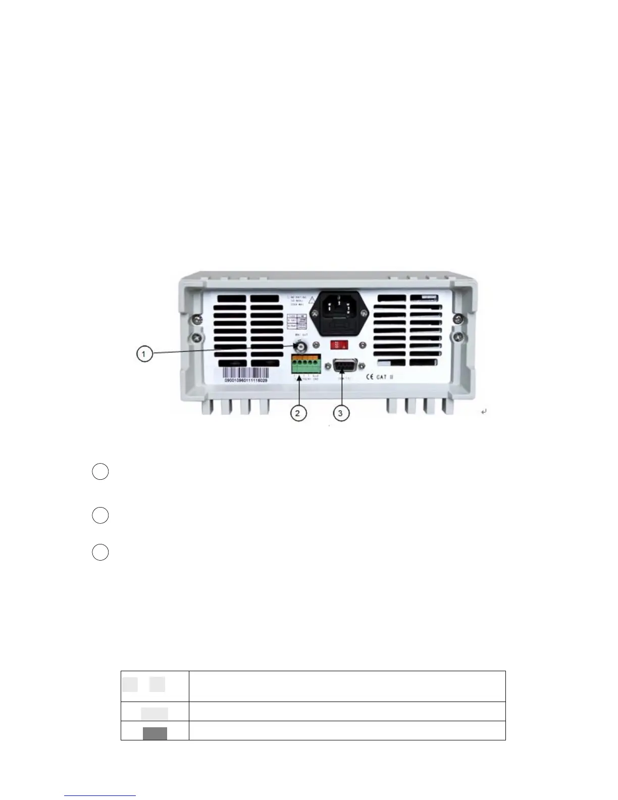
Diagram 3.3 the back panel of the M97XX Series DC electronic load
BNC Out connector for 0-full range current, that corresponds to 0-10V output.An Oscilloscope
can be connected here to view dynamic waveforms.
Remote Measurement terminals and trigger for input/output interface
DB Sub 9 pin multifunctional communications interface for RS232, RS485 and USB serial buses
(with optional M133 D sub 9 to USB conversion cable). Do not connect an M131 cable with
standard RS-232 voltages on the cables connectors. Doing so may damage the instrument
and is not covered by WARRANTY.
3.4 Keypad Directions
1
~
9
0-9 numeric keys
Esc
Esc key (enables exit from any working condition/mode)
I-Set
Switch to CC mode
22
33
11