24
constant power mode, constant resistance mode, short circuit mode. Four comparison choices are
available: current comparison,voltage comparison, power comparison and resistance comparison.
Moreover, the delay time of each step can also bevaried. The delay time of each steprange from
0.1~25.5S, depending on the quickness and accuracy required. When each automatic test is over, the DC
electronic load will indicate a pass or a fail result.. The electronic load will sound an alarm when a UUT fails
a test. The trigger function of the electronic load can be set at the front-panel for TRIGGE IN for the
hardware voltage level in from the back-panel terminal connector, and TRIGER OUT for voltage level out
from the terminal connector on the back panel. The trigger mode can be set up as either voltage level
trigger or pulse trigger, and has 4 selection options of pass trigger, fail trigger, test completetrigger and
disable- trigger.
4.2.8.1 Automatic Test Operation
1)Press Shift+0 keys to enter menu configuration, and then use the ▲ and ▼ keys to reach
MENU AUTO TEST, and press Enter to confirm. Using press the ▲ and ▼ keys, go toEDIT AUTO TEST,
and press Enter.. Now use the ▲ and ▼ keys to select the sequence steps desired and then press Enter.
2) When STEP LENG= XX, appears, set the desired step length. Use the numeric keys to input
the step length, and press Enter. Note: step lengths should be a round number between1~50.
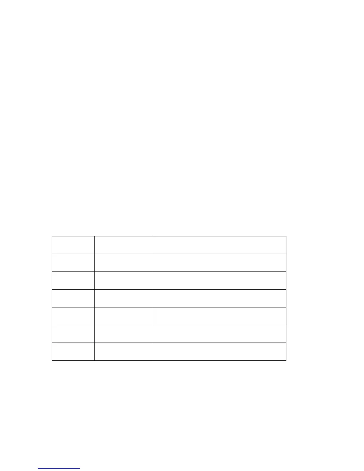
3) At STEP 1 xxxxx MODE, use the▲ and ▼ keys to select from the following six working
modes,
then press Enter.
Working
Mode
Promp Messages Explanation
Load Off
Mode
LOAD OFF MODE”
Compares the voltages when in load off mode
CC Mode “CC MODE” Choose one of four comparison types: current,
voltage, power or resistance
CV Mode “CV MODE” Choose one of four comparison types: current,
voltage, power or resistance
CP Mode “CP MODE” Choose one of four comparison types: current,
voltage, power or resistance
CR Mode “CR MODE” Choose one of four comparison types: current,
voltage, power or resistance
Short Circuit
Mode
“SHORT MODE” Compares the current when in short circuit mode
4) At STEP 1 TEST xxxx, there are four test types to select from: current, voltage, power and
resistance. Use the ▲ and ▼ keys to select one from the four test types, and Enter.If in the previous
step, if either load off mode or short circuit mode, was selected, then the electronic load will skip step over
this step 4).
5)At DELAY TM=xx.xS”,indicating the delay time input for each step, the valid range is between
0.1~25.5S. . The lower the value set, the shorter the duration of the test. Caution: in certain cases, if the
value set is too low, the test result might be compromised because the test was ended before the power
supply under test reaches its static state., To assure valid test results, select the delay time within optimal
duration for best results.The recommended delay time is 0.5S. Note: The upper range of 25.5S is pre-set