25
as a test suspended mode. Setting the delay time of any certain step at 25.5S, the load will stop and not
proceed to the next step until a trigger signal is provided to continue the test. The trigger signal can be
made either by the hardware on the back-panel, or by using the Shift+Trigger or the On/Off keys on the
VFD display panel.
6)WhenINPUT xxxx=xxxxxx, is displayed, it indicates the corresponding current, voltage, , power
and resistance values in the working mode that have been set. Use the numeric keys to enter these values,
and press Enter to confirm. Again, if in the prior step 3), load off mode or short circuit mode had been
selected, the DC electronic load will skip over this step 6).
7) When MINIMUM xxxx=xxxxxx, appears, it indicates the lower limit value of a valid test
comparison. Use the numeric keys to input the value, and press Enter to confirm. When the VFD display
shows MAXIMUM xxxx=xxxxxx, the upper limit value of a valid test comparison is shown. Use the
numeric keys to input the value, and press Enter to confirm.
When EDIT AUTO TEST is displayed on the screen, all the steps set requiring input values have
been completed., the The DC electronic load will exit back to the automatic testing function. But if all the
stepshave not been properly selected and values entered STEP n xxxxx MODE will be displayed
indicating that some data of the N step needs to be keyed in.
4.2.8.2 Setting up Automatic Test Trigger Output Mode
Press Shift+0 keys to enter the menu configuration mode, and using the ▲ and ▼ keys to get
to MENU AUTO TEST, and press Enter.Scroll the ▲ and ▼ keys to get to SETUP AUTO TEST, and
press Enter.The DC electronic load will be in automatic test trigger output mode.
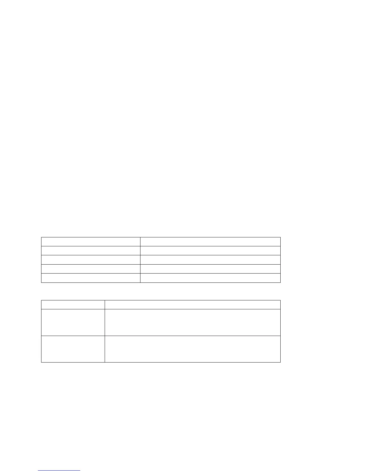
There are 4 types of trigger output modes shown in the table below. Using the ▲ and ▼
keys,select the mode desired and press Enter.
Promp Messenges Explanation
“TRIGGER WHEN PASS” Test passed result
“TRIGGER WHEN FAIL” Test failed result
“TRIGGER WHEN TEST END” Test completed
“TRIGGER DISABLE” Trigger disabled
Meanwhile, the Load will display the following trigger output electrical feature
Display Description
“OUTPUT LEVEL” Upon trigger, the output, voltage level will change from low to
high, until a key is pressed or a trigger input signal arrives, and
the voltage level then drops to low status.
“OUTPUT PLUSE” Upon trigger the output voltage level changes from low to high
status, and after 5 seconds
automatically drops to a lower level
4.2.8.3 Executing Automatic Test Function
Using both the Shift+0 keys go to menu configuration, and then press the ▲ and ▼ keys to
get to MENU AUTO TEST, and press Enter. Scroll with the ▲ and ▼ keys and get to LOAD AUTO TEST,
and press Enter.. Use the ▲ and ▼ keys to select the sequential code for the automatic test function you
want to execute, then press the Enter The top right corner of the VFD two line display shows
AUT n, meaning the n automatic test in the list will be initiated. The bottom right of the VFD shows OFF D.
If all settings have been entered correctly, press the On/Off key to initiate the automatic test.
The automatic test can also be initiated by lowering the voltage level of TRIG IN port with a duration of
more than 5mS. When in testmode, the lower right corner of the VFD display will show WAIT or STAY,