14
I
V
Load input voltage
I
V
Load input voltage
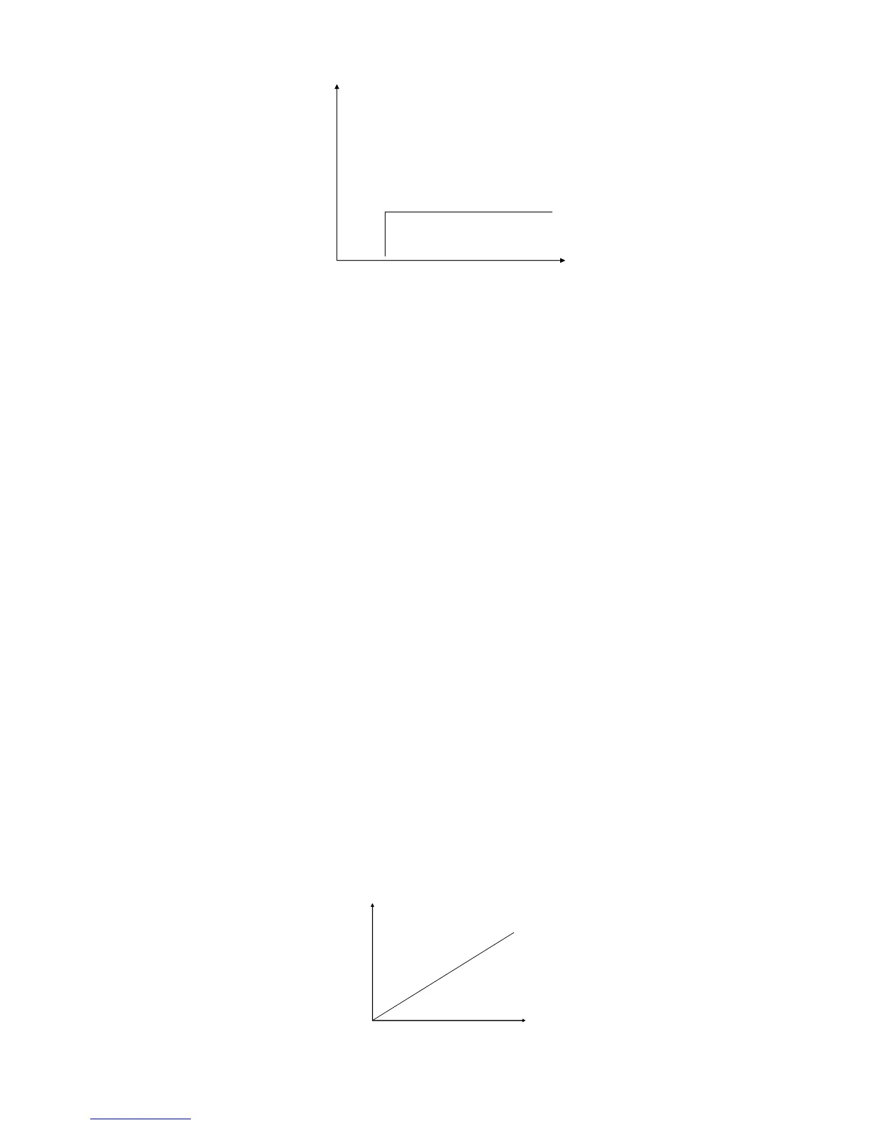
Diagram 4.4 Constant CurrentShift Mode back into Constant Voltage Mode
When in standard constant current mode, press the Shift+4(CC+CV) keys to enter into the constant
current shiftto constant voltage mode. When the VFD display shows CC TO CV VOLT=xxxxxxxxV
indicating the current constant voltage value, press the numeric keys and decimal point key to enter the
constant voltage value desired followed by pressing the Enter key to confirm. Now the load will enter into
the constant current shift mode into constant voltage mode.
If the input state is in OFF , then the upper right corner of the VFD display will show the word OFF.
Press the On/Off key to change the input state into ON. The upper right corner of the VFD display will
show the combination ofCC+CV or Unreg. When CC+CV is displayed, the DC Electronic load has been
successfully set into the desired CC value; by displaying Unreg means the load could not adjust itself to
the selected CC value. Check that the unit under test has been connected correctly and powered on. Also,
assure that voltage level is normal.
When in the loading and unloading constant current mode, pressing the Shift+4(CC+CV)keys will
make the load revert back into the standard constant current mode.
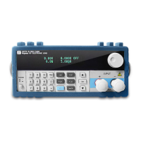
4.1.2 Constant Resistance Operation Mode (CR)
In this mode, the DC Electronic Load will synchronize to a current linearly proportional to the input
voltage scaled to- the resistance programmed. Please refer to the Diagram 4.5.
Note: when the voltage of the unit under testis set too high and the resistance set is too low, either
the unit under test will consume the excess current and be shock damaged, or the DC Electronic Load will
fail to automatically adjust to the constant resistance and the load will suffer the shock damage from the
excess current.
I
V
Load current
Load input voltage
Slop resistance set
I
V
Load current
Load input voltage
Slop resistance set