21
10A
5A
10ms
TWD
10ms
TWD
TRIG TRIG
10A
5A
10ms
TWD
10ms
TWD
TRIG TRIG
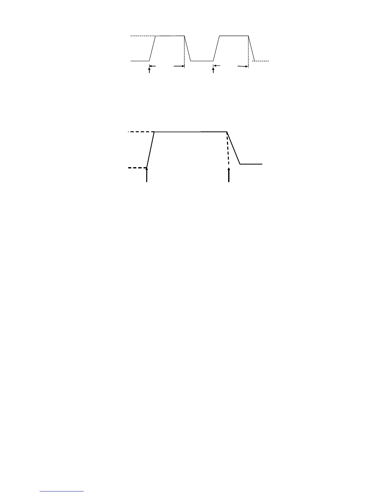
Diagram 4.11 Pulse Operation Mode
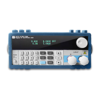
4.2.3 Trigger Mode(TRIGGER)
In this mode, when the dynamic test operation is turned on, the DC electronic load will switch the state
between value A and value B afterreceiving a trigger signal.
10A
5A
TRG
TRG
10A
5A
TRG
TRG
Diagram 4.12 Trigger Operation Mode
4.2.4 Setting up Dynamic test operational Parameters
Press the Shift+6(S_Tran) keys, and the DC Electronic Load's VFD display shows LEVEL A
CURR=xxxxxxxxA indicating value A's current setting. Use the numeric keys and decimal point key to
select the current value desired, followed by pressing the key Enter to confirm the setting.
When the load VFD display shows WIDTH A TM=xxxxxxxxmS, it indicates the current duration time
of current set for value A.. Using the numeric keys and decimal point key, enter the duration time desired,
then press the Enter key to confirm.
When the DC Load's display shows RISING TM=xxxxxxxxmS, it indicates the current rise time set
from value A to value B. Use the numeric and decimal point keys to enter the rise time desired, and press
the Enter key to confirm.
Next the DC Load's display shows LEVEL B CURR=xxxxxxxxA that indicates the current value B
setting. Use both the numeric and decimal point keys to enter the current value desired, and press the
Enter key to confirm.
When WIDTH B TM=xxxxxxxxmS appears on the display panel it indicates the current duration
interval forvalue B that's set. To enter a different value for current, press the numeric and decimal point
keys to enter the duration period desired, followed by pressing the Enter key to confirm.
Next the DC Load'sVFD panel displays FALLING TM=xxxxxxxxmS which indicates the current falling
off time presently set between value B to value A. To change that value, use both the numeric and decimal
point keys to enter the falling off time desired, and press the Enter key to confirm.
After all of these parameters have been set, the DC Electronic Load's panel will display the set-up of
TRANMODE CONTINUOUS/ TRANMODE PULSE / TRNMODE TRIGGER indicating the unit is currently