20
the numeric selector keys and decimal point key to enter the unload voltage valuedesired, followed by
pressing the Enter key to confirm. Now the load will be in the loading and unloading constant power mode.
If the input state is OFF, then the upper right corner of the VFD display will show OFF. Press the
On/Off key to change the input state to ON. Now the upper right corner of the VFD panel will display either
CW_UN or Unreg. CW_UN means the DC Load has been successfully set with the desired constant
power value; Unreg means the DC Load did notaccept the desired constant power value. Please check
thatthe LED driver under test has been correctly connected and powered on; make sure that its voltage is
normal and that its output current is within the range ofcurrent that the DC Load'sselected power
canwithstand.
From the load and unload constant power mode, press the Shift+1(V_Level) keys, and the DCLoad
will revert back to the standard constant power mode.
4.2 Dynamic Testing Operation
Dynamic testing operation enables the DC electronic load to periodically switch between two pre-set
load levels. This function can be used to test the transient characteristics of the LED driver being tested.
Dynamic testing operation can be turned on and off by pressing the
Shift
+
Tran
keys on the
front panel. Before turning dynamic testing operation on, all of the parameters associated with dynamic
testing operation should be set by pressing the
Shift
+
S-Tran
, keys including: Value A, A pulse time ,
Rise time from value A to value B, Value B, B pulse time, Fall time from value B to value A and dynamic
testing operation mode. There are three modes of dynamic testing operation: continuous, pulsed and
triggered modes.
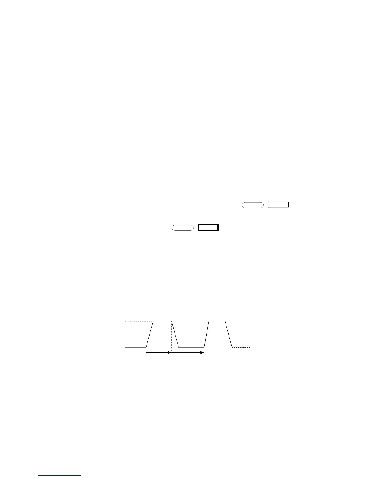
4.2.1 Continuous Mode (CONTINUOUS)
In this mode, when the dynamic test operation is turned on,the DC electronic load will periodically
switch between values A and B.
10A
5A
2.0ms 3.0ms
10A
5A
2.0ms 3.0ms
Diagram 4.10 Continuous Operation Mode
4.2.2 Pulsed Mode (PULSED)
In this mode, when the dynamic test operation is turned on, the DC electronic load will switch to value
B when receiving one triggered pulse signal , then capture the pulse time(TWD) of value B , after which the
DC Electronic Load will return to Value A .