23
SOURCE UNIT INSTALL
INSTALLING THE SOURCE UNIT (Non-Ride Command-Equipped)
Reassemble part of the front dash around the dash pocket area. Utilize the reverse method of how you
removed the center section of the dash pocket. This will allow the source unit mount to be to be installed in
place so the harness can be nished and connected in the proper location. Final tting and reassembly of all
panels is the last step of the installation after testing the system.
STEP 1 – RUN CONNECTIONS TO SOURCE UNIT AREA
Run the (2) RCA audio cables from the amplier location into the area where the source unit will be installed.
Be sure to observe left and right channels at the amplier. Make note of which connects to the two-channel
amplier and which connects to the mono amplier.
Next, if not already done, run the source unit connectors to the area where the source unit will be installed.
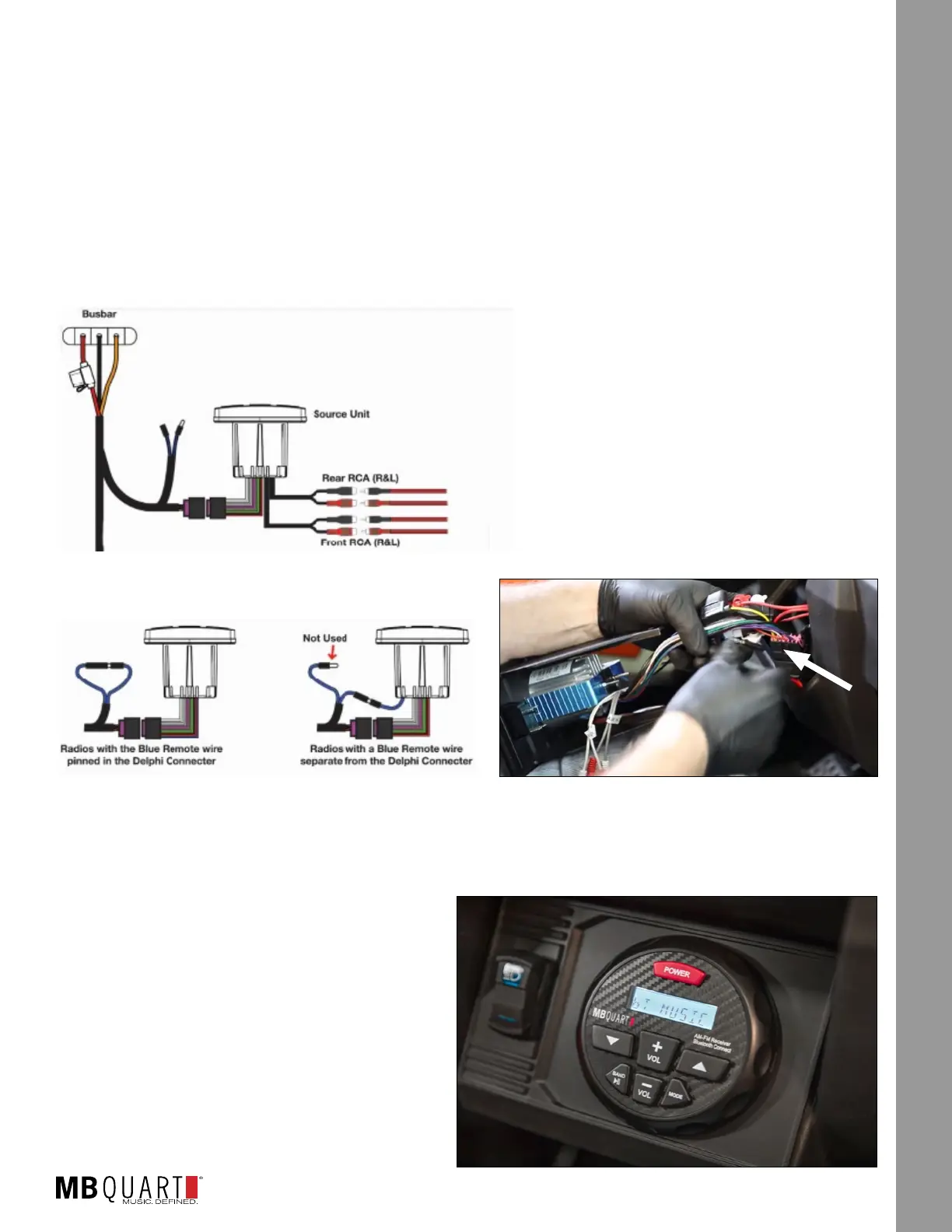
STEP 2 – MAKE SOURCE UNIT CONNECTIONS
With the harness routed through the vehicle and everything
connected to the amplier(s), the next step will be to
make the nal source unit electrical and RCA audio cable
connections in the dash as shown in
Figure 17-1a. Raise the completed source
unit mount to the dash area. Connect the
electrical (Delphi-style) connector. Connect
the front RCA preamp level outputs to the
two-channel amplier. Connect the rear RCA
preamp level outputs to the mono amplier.
Depending on the style of remote turn-on present on your source unit, follow Figure 17-1b for the
connection. Figure 17-1c shows the connections to the source unit in the dash.
NOTE – As you raise the completed source unit to the dash area, ensure you retained and installed the
metal clip described in the previous section.
STEP 3 – SECURE THE SOURCE UNIT
Push the dash assembly into place until you feel
and hear a snap as the entire assembly seats
into place. The nished look should cosmetically
resemble Figure 17-2.
Powering up the system and initial testing will be in
a subsequent step.
Figure 17-1a
Two-
Channel Amp
Mono
Amp
Figure 17-1b
Figure 17-1c
Figure 17-2