A
DANGER -
A
ALWAYS STOP ENGINE AND DISCONNECT SPARK
PLUG WIRE AND MOVE ITAWAY FROM
SPARK PLUG
BEFORE PERFORMING ANY ADJUSTMENTS OR RE-
PAIRS.
WHENCLEANING, REPAIRINGORINSPECTfNGYOUR
CHIPPEWSHREDDER MAKE CERTAIN ALL MOVING
PARTS HAVE STOPPED.
TO REDUCE THE RISK OF INJURY, ALWAYS WEAR
HEAVY GLOVES WHEN HANDUNG THE CLflllNG
BLADES.- THE CUITiNG EDGES ARE
SHARP AND
CAN
CAUSE SEVERE INJURY.
SHARPENING OR REPLACING
CHIPPER BLADES:
Over a period of time, the cutting blade will dull. Sharpen or
replace the blade when the chipper no Iongw cuts as efficiently
as when new.
● Discard a cracked or severely nicked blade because it
could break apart and cause personal injury.
● Sharpen a blade that isdullorthat has only minor nicks; The
blade is made from tempered steel and is extremely hard -
do not attempt to sharpen with a hand file. We recommend
that you take the blade to a professional sharpening service
for proper sharpening.
Allgrinding must be done flat and
uniform along the beveled edge only, being sure to maintain
the orginal 45° cutting angle.
TO REMOVE AND INSTALL THE
CHIPPER BLADE:
Disconncd spark plug wire and move it away from spark
plug.
Ftemove the Chipper chute by removing three (3) hex nuts
and washers (iorns B). A 1/2” sockot with ~xtension is
required (Soo FIG.-3 ASSY).
Rota! e the Hopper assembly to the ground as shown in FIG.
3-OP.
Removo tho three (3) hex locknuts (item A) and flatwashers
(iem B) from the housing studserts and carefully separate
the Hopper assembly from the remainder of the unit (See
FIG. 2-SERV. & ADJ.)
Remove the three
(3) bushings (item C) and stationary
plate
(item D). (See FIG. 2-SERV. & ADJ) NOTE: When
reassembling, make certain the opcximg of the stationary
plate is toward the bottom of the unit and the offset, is facing
toward the impeller assembly.
Rotate the impeller assembly by hand until you locate the
Chipper blade in the Chipper chute opening.
Prevent” the impeller ,assembly from turning in a
counterclockwise direction by wedging a block of wcod
be[wecn one of the fan blades and the wall of the’housing
or, insert a thick, hardwood dowel (item A) through the slot
below the blade and into the Chipper chute opening in the
wall of the housing. (See FIG. 1-SERV & ADJ).
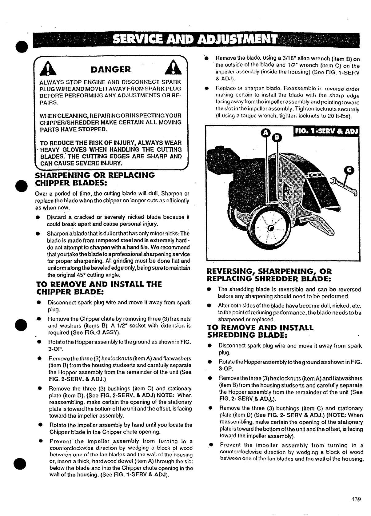
● Remove the blade, using a
3/16- anon wrench (item B) on
the outside of tho bfade and 1/2” wrench (item C) on [he
impeller assembly (inside the housing) (See FIG. 1-SERV
&
AD.f).
. Replace 01 sharpen blade. f30assomblo in rowrse order
m;+king certain 10 inslall the blade with the sharp edge
facing away from the impellorassomtiy and pointing toward
the sfot in the impeller
assembly. Tghten locknuts securely
(if using a torquo wrench, tighten lo~nuts to 20 ft-lbs). -
● The shredding bfade is reversible and can be reversed
before any sharpening should need to be performed.
● After both sides of the blade have become dull, nicked, etc.
to the point of reducing performance, the blade needs to be
sharpened or replaced.
TO REMOVE AND INSTALL
SHREDDJNG BLADE:
●
●
●
●
●
Disconnect spark plug wire and move it away from spark
plug.
Rotate [he Hopper assembly totheground as shown in FIG.
3-OP.
Remove the three (3) hex locknuts (iem A) and flatwashers
(item B) from the housing studserts and carefully separate
the Hopper assembly from the remainder of the unit (See
FIG. 2- SERV,& ADJ.).
Remove the three (3) bushings (i[em C) and stationary
plate (item D) (See FIG. 2-
SERV & ADJ.) (NOTE: When
reassembling, make certain the opening of the stationary
plate is toward the bo[~om of the uni[ and the offset, is facing
toward the impeller assembly).
prevent the impeller assembly from turning in a
counterclockwise direction by wedging a block of wood
between one of the tan blades and the wall of the housing.
439