Reel Disk from McFarlane Mfg. 26 800-627-8569
Note: As viewed from the front of the unit, turning the
turnbuckle counterclockwise will raise the hitch
end and lower the spiral reel end.
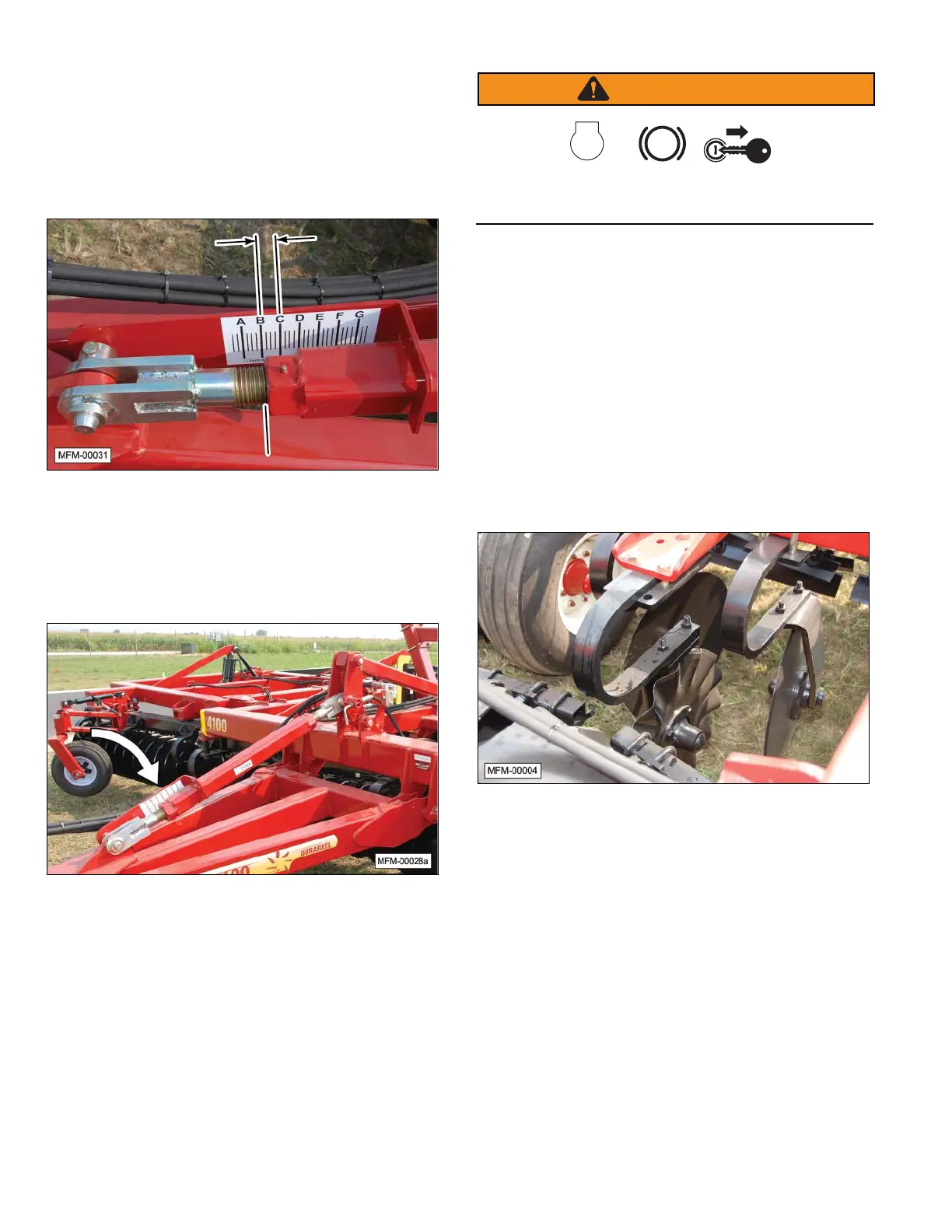
c. Record the current location on the depth gauge
(B0) that is located on the turnbuckle lock. Each
mark on the depth gauge represents a 1” change in
disk depth. Example, changing from B0 to C0 will
produce 4 inches of change.
d. Check the frame for level. Adjust the turnbuckle as
needed.
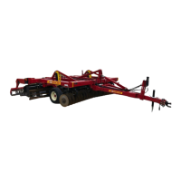
e. Once the unit is level from front to back, and the
disks are cutting at the desired depth, place the
locking mechanism over the turnbuckle.
Note: When a major change is made to the depth of the
front gang disks or the spiral reels, make sure the
frame is still level.
8. Stop the tractor with the unit still in the ground.
WARNING
STOP
P
Before leaving the tractor, shut off the engine, set the
parking brake, and remove the ignition key.
9. Measure the depth the disk is cutting into the ground.
Note: The desired depth (no more than 4 inches) of the
disks is controlled by a hydraulic valve. When
the wheels of the unit are raised, the stop crank
actuates the valve, stopping oil fl ow. Each time
the wheels are raised and lowered, the valve will
consistently position the depth of the unit.
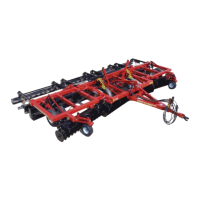
10. Adjust the angle of center disks, if necessary. Adjust
the center disks with more or less angle to prevent
ridges or gaps from forming between the two inner
disk gangs. Also, the depth of the coulter disk can be
changed by adding or removing spacers.
Note: It may only be necessary to change the angle of
the center disks when the disk gangs are set to
steeper angles. The angle of the center disks can
also be changed by loosening the back bolt of
the mounting bracket and twisting to the desired
angle.