6
Where to put it
The C8 can be placed upright on a table or shelf,
standing on its four feet. It also can be custom
installed in a piece of furniture or cabinet.
Always provide adequate ventilation for your C8.
Cool operation ensures the longest possible operating
life for any electronic instrument. Do not install the
C8 directly above a heat generating component such
as a high-powered amplier. If all the components
are installed in a single cabinet, a quiet running
ventilation fan can be a denite asset in maintaining
all the system components at the coolest possible
operating temperature.
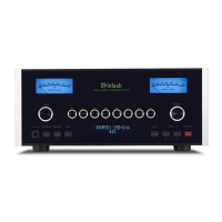
A custom cabinet installation should provide the
following minimum spacing dimensions for cool
operation (see Figure 02):
• 6 inches (15.3cm) above the top
• 5/8 inches (1.6cm) below the bottom
• 2 inches (5.1cm) on each side of the C8 so that
airow is not obstructed
• 18 inches (45.7cm) depth behind the front panel
• 1-7/16 inch (3.7cm) in front of the mounting
panel for knob clearance
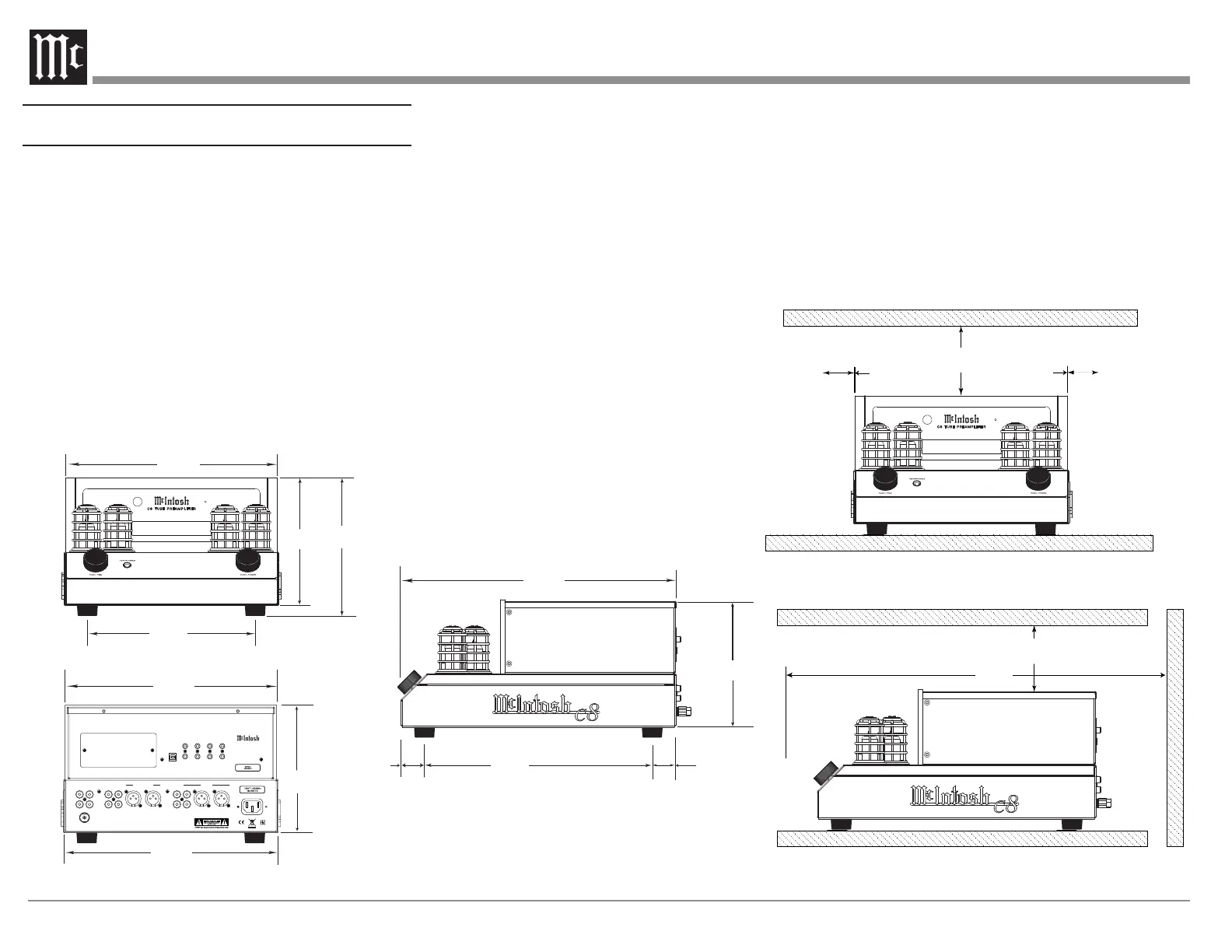
1-5/16"
1/32
1/32
11-7/8"
30.2cm
Rear View of the C8
11-1/2"
29.2cm
12 - "
30.6cm
7-5/8"
19.4cm
7-1/32
17.9cm
7- "
17.9cm
7-1/32"
17.9cm
3.36cm
12-3/4 "
32.4cm
3.3cm
Side View of the C8
15-3/8"
VOLUME
INPUT
HEADPHO NES
PUSH - TRIM PUSH - POWE R
C 8 T UB E P R E AM PL IF IE R
PHONO INPUTS
MC MM
UNBALANCED INPUTS
1 2
BALANCED INPUT
R
L
OUTPUT 2
(SUB) UNBAL
OUTPUT 1
BAL R BAL L
GND
L
R
L
R
L
R
SERVICE
PORT
McINTOSH LABORATORY, INC., BINGHAMTON, NY
HANDCRAFTED IN USA WITH US AND IMPORTED PARTS
C8 TUBE PREAMPLIFIER
DATA
PORTS
EXTERNAL
CONTROL
POWER CONTROL
1 MAIN TRIG 1
2 PASSTHRU TRIG 2
RS232
IR IN
Front View of the C8
9-3/8"
23.8cm
"
39.0cm
1-5/16"
Figure 01– C8 Dimensions
Figure 02– Ventilation requirements
18"
45.7cm
6"
15.3cm
6"
2"
5.1cm
2"
5.1cm
15.3cm
VOLUME
INPUT
HEADPHO NES
PUSH - TRIM PUSH - POWE R
C 8 T U B E P R EA MP LI FI ER