Extreme 9" Monitor/DVR System© 2014 McNeilus Truck and Manufacturing, Inc.
10
Installation
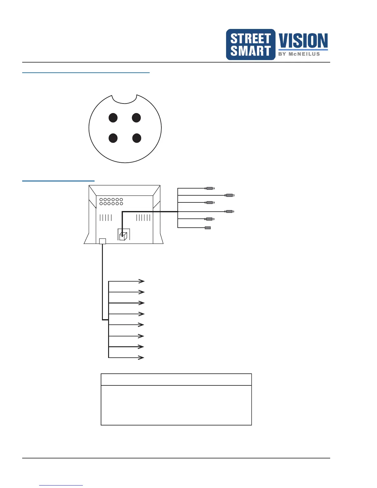
Camera Connection Pin Assignment
3
2
Image displays the pin
assignment from the monitor
side to the camera connector.
Pin Assignments:
Pin 1 = GND (Ground)
Pin 2 = +12V (Power)
Pin 3 = Video
Pin 4 = Audio
Connection Diagram
Power
Accessory
Harness
Master
Cable
Harness
CAMERA A REVERSE
CAMERA B LEFT
CAMERA C RIGHT
CAMERA D FRONT
CAMERA E PARK
GPS ANTENNA CONNECTION
RED for ACC to connect to Ignition Power Source
BLACK for Ground
YELLOW for connection to Battery
GREEN for connection to trigger Camera A
PURPLE for connection to trigger Camera B
BROWN for connection to trigger Camera C
BLUE for connection to trigger Camera D
GRAY for connection to Camera E
NOTE
The yellow wire must be connected to the battery
or a constant power source to ensure your monitor
settings are retained and also to allow certain
recording options to function when the LCD screen
is turned off (see Ignition Off Setup).


 To Next Page