Extreme 9" Monitor/DVR System© 2014 McNeilus Truck and Manufacturing, Inc.
60
Preco Preview Radar System
• Install All Cables
1. Route the body cable (P/N 1504310) along the side of the vehicle starting from the PreView
®
sensor at the
rear of the vehicle to the cab (Figure 36 and 37).
• Leave a small service loop in the cable at the sensor at the rear of the vehicle
• Do not route cable next to heat sources
• Do not route cable in areas that may see abrasion, rock, or debris damage
• Bundle and store any excess cable away from areas that may damage it
• Secure the cable every few feet (approximately every 1M) with tie wraps
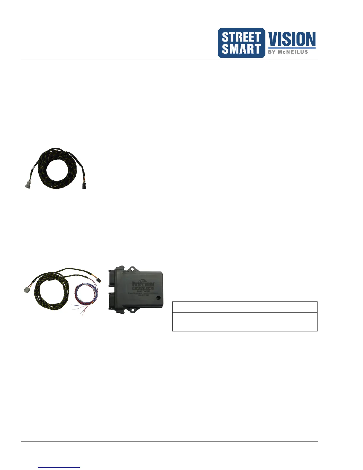
Figure 36: Body Cable (P/N
1483945)
2. Connect the Cab Adaptor Cable 16' (4.9M) (P/N 1483928) to the body cable and the VideoLink module
(Figure 37). From the Cab Adaptor Cable, connect the red wire to +12/24 VDC Input Power, the black wire
to ground, and the blue wire to reverse light power circuit. The white wire will be connected to the Buzzer
after it is installed.
3. Turn on the SSV Extreme Monitor/DVR System to verify the PreView
®
system is operational.
Figure 37: Connect Cab Adaptor Cable (P/N 1483928) to
VideoLink
NOTE
The sensor mating connector is fully waterproof if
mated properly.
 Loading...