© 2008 McNeilus Truck and Manufacturing, Inc.
Rear Loader
39
Operation
1.0 Instruments and Controls
The following gures and tables identify and describe the
controls used on the equipment. Not all of the instruments and
controls shown here are on your equipment. Items covering
various models and options are illustrated.
To make sure you understand proper operating procedures,
read this section and carefully practice with the controls and
instruments to learn how to safely operate the equipment.
1.1 Cab Controls
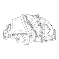
The in-cab controls consist of a control panel mounted either
between the seats, in the dash, or under the dash, depending
on chassis conguration (Figure 5, Item 1).
Figure 5
No. Position Normal Use or Reading
2
E-STOP
Button
Disables all hydraulic and electric refuse vehicle
Functions with the exception of the lights and
alarms.
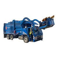
The E-STOP button (Figure 5, Item 2) has two
positions: IN and OUT (Figure 6).
Push IN to disable operation of functions.
Pull OUT to enable operation of functions.
If your rear loader has the optional side
door ladder, the door will be equipped with a
proximity switch. If the side door is open, the
proximity switch stops Hydraulic Functions
during normal operation. To resume Hydraulic
Functions, ensure the side door is closed and
the control box E-STOP is in the OUT position.
1
Figure 6