8 AGZ 010B through 034B IOMM AGZB1
Figure 4, Typical Field Evaporator Water Piping
Vent
Outlet
Inlet
P
Valves
NOTES:
1. Chilled water piping within the unit enclosure must be insulated in the field.
2. Support piping independently of the unit and install per local codes.
System Volume
It is important to have adequate water volume in the system to provide an opportunity for
the chiller to sense a load change, adjust to the change and stabilize. As the expected load
change becomes more rapid, a greater water volume is needed. The system water volume is
the total amount of water in the evaporator, air handling products and associated piping. If
the water volume is too low, operational problems can occur, including rapid compressor
cycling, rapid loading and unloading of compressors, erratic refrigerant flow in the chiller,
improper motor cooling, shortened equipment life and other undesirable occurrences.
For normal comfort cooling applications, where the cooling load changes relatively slowly,
we recommend a minimum system volume of three to four times the flow rate (GPM). For
example, if the design chiller flow rate is 120 GPM, we recommend a minimum system
volume of 360 to 480 gallons.
Since there are many other factors that can influence performance, systems may
successfully operate below these suggestions. However, as the water volume decreases
below these suggestions, the possibility of problems increases.
Variable Chilled Water flow
Variable chilled water flow systems are not recommended for this class of equipment due to
limited unloading capability.
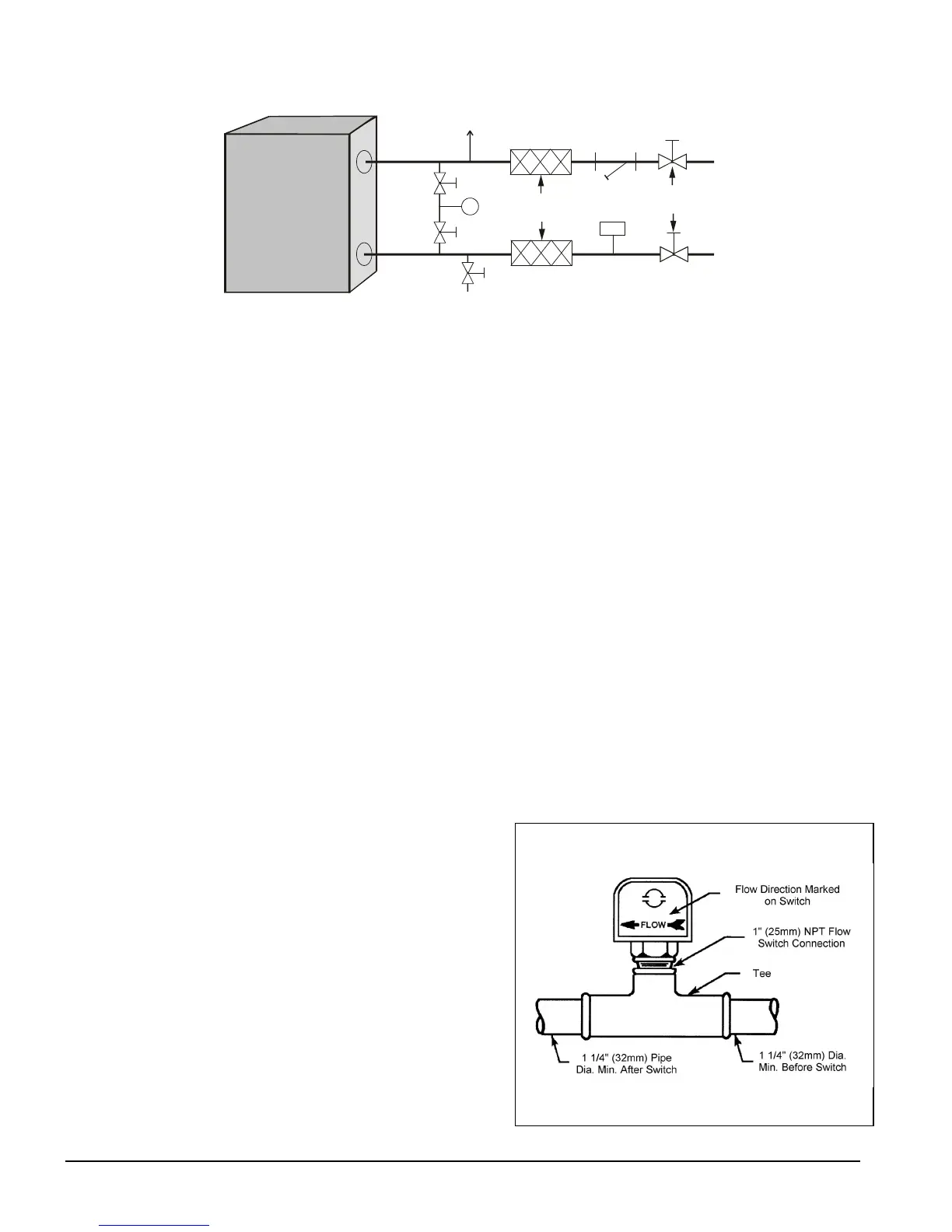
Flow Switch
Mount a water flow switch in the leaving water line to shut down the unit when water flow
is interrupted.
A flow switch is available from
McQuay (part number 017503300). It
is a “paddle” type switch and adaptable
to pipe sizes down to 1 1/4” (32mm)
nominal. Certain minimum flow rates
are required to close the switch and are
listed in Table 2. Install the switch as
shown in Figure 5. Connect the
normally open contacts of the flow
switch in the unit control center at
terminals 4 and 5. There is also a set of
normally closed contacts on the switch
that can be used for an indicator light or
an alarm to indicate when a “no-flow”
Figure 5, Flow Switch Installation

 Loading...


