IM 781-2 Page 21
LONWORKS communication connections to the CSM are to be made to a single orange 2-position screw terminal connector
on the top left of the main control board. See the Main Board Layout (see Figure 29) for locations of these terminals.
Wire this connector to the L
ONWORKS communications modules on all of the chillers and remote I/O modules controlled
by the CSM.
!
CAUTION
Do not run LONWORKS communication wiring with high-voltage supply or relay cables. The high-voltage can cause
erratic operation of the L
ONWORKS network. Local wiring codes may take precedence over this recommendation.
Free Topology Networks
Each Lon network node (chiller, CSM, Remote I/O Module) must be equipped an FTT-10A transceiver for network
communication. For each MicroTech II chiller, an optional L
ONWORKS Communication Module includes the required
FTT-10A transceiver. This transceiver allows for (1) free topology network wiring schemes using twisted pair (shielded or
unshielded) cable and (2) polarity insensitive connections at each node. These features greatly simplify installation and
reduce network-commissioning problems. Additional nodes may be added with little regard to existing cable routing.
A L
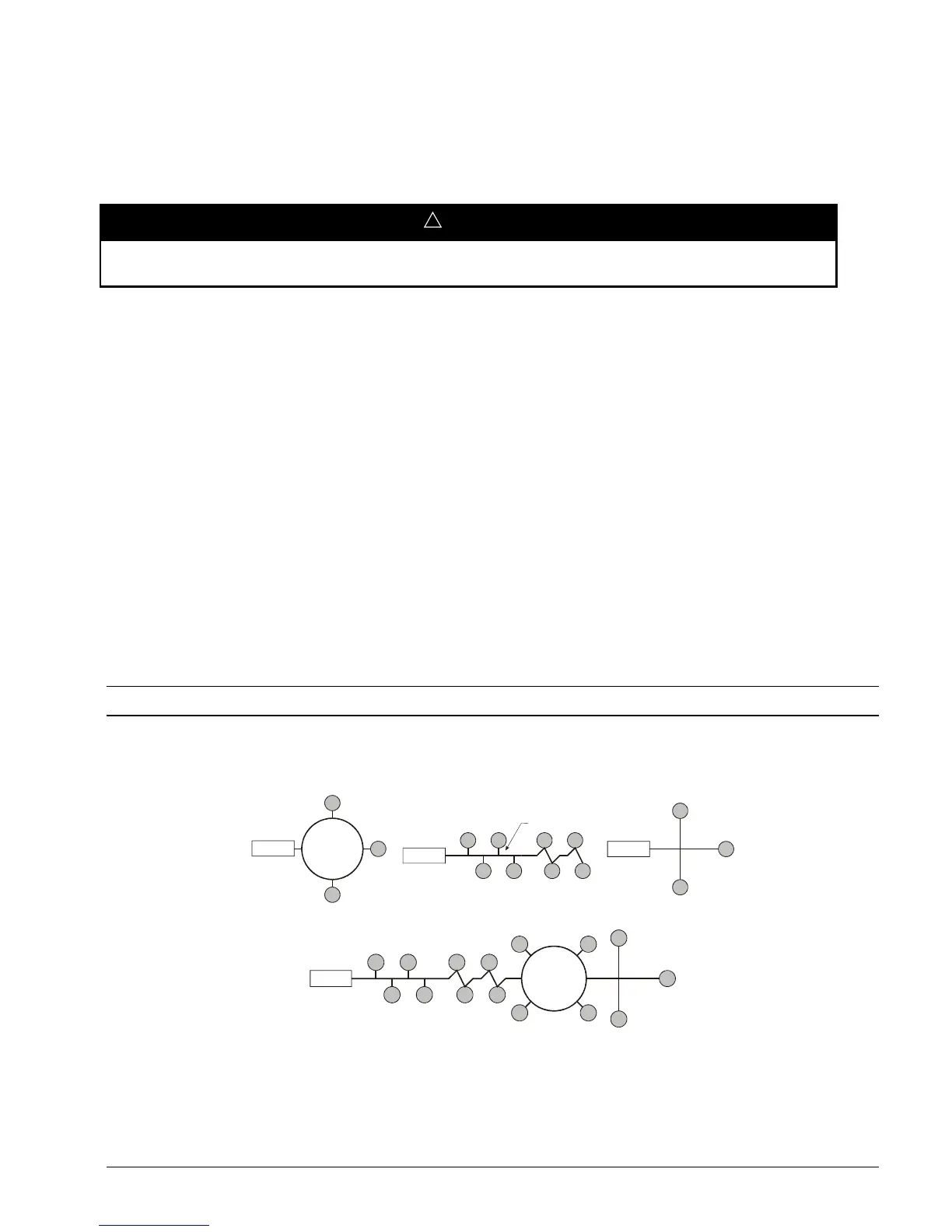
ONWORKS “free topology network” means that devices (nodes) can be connected to the network in a variety of
geometric configurations. For example, devices can be daisy-chained from one device to the next, connected with stub
cables branching off from a main cable, connected using a tree or star topology, or any of these configurations can be
mixed on the same network,
as shown in Figure 17. Free topology segments require termination for proper transmission
performance. Only one termination is required and may be placed anywhere along the segment. Refer to Echelon’s
L
ONWORKS FTT-10A Transceiver User’s Guide (Echelon document number 078-0156-01G).
Free topology networks may take on the following topologies:
•
Bus
•
Ring
•
Star
•
Mixed - Any combination of Bus, Ring, and Star
Note: Limitations to wire lengths apply and must be observed.
Figure 17. Singly Terminated Free Topology
Termination
Star Topology
Termination
ng
opo
ogy
Termination
Singly Terminated Bus Topology
Stub
}
Termination
Mixed Topology
A network segment is any part of the free topology network in which each conductor is electrically continuous. Each of the
four diagrams is an illustration of a network segment. Some applications may require two or more segments (see Free
Topology Restrictions below). If necessary, segments can be joined with FTT-10A-to-FTT-10A physical layer repeaters.
Refer to Echelon’s L
ONWORKS FTT-10A Transceiver User’s Guide (Echelon document number 078-0156-01G).

 Loading...


