IM 781-2 Page 29
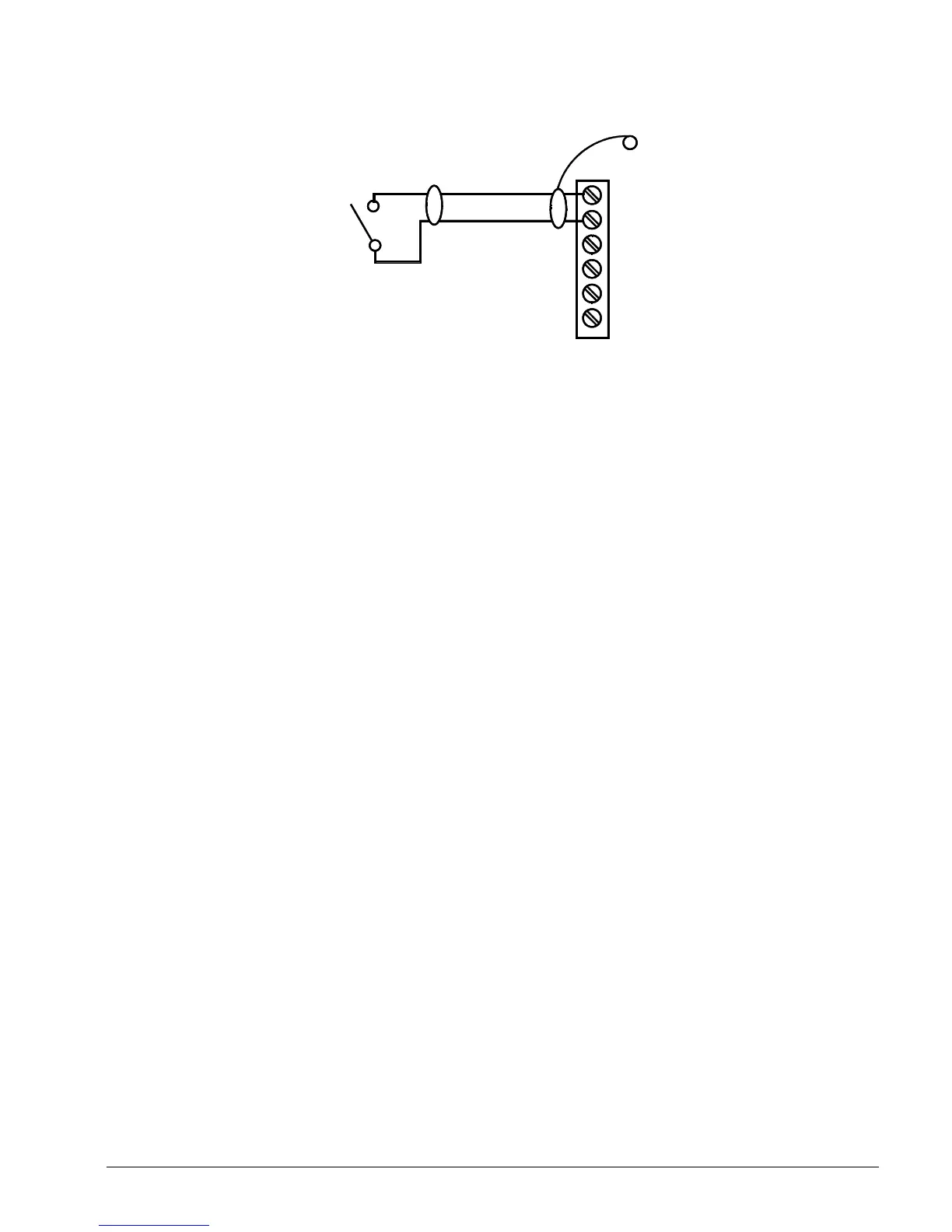
Figure 23. Digital Input Wiring
UI1
G
UI2
Shield
Stud in
enclosure
200' max
Shielded, Twisted
Cable
Use object: NdioBinaryInput
Dry
Contracts
1. External Start/Stop (UI 13)
External start/stop may be used when manual schedule override or external time clock scheduling is required.
Using manual schedule override (a switch) or external time clock scheduling, the CSM will begin the start-up of the chillers
when the external input is closed. The CSM will begin the shutdown of the chillers when the external input is open.
2. Chilled Water Reset Override (UI 14)
Chilled water reset override is an option that allows the CSM to override any reset method that is being used. When the
chilled water reset override input is closed, the chilled water supply setpoint will be set to an adjustable minimum value.
Outputs
External devices can be controlled by the digital outputs of the CSM’s onboard I/O panels. These digital outputs are used
for alarm signaling and to enable cooling load pumps.
The CSM’s onboard digital outputs are isolated dry contact relay output closures, 24-VAC/dc at 2 A resistive. An LED
indicates the status of each output. Each relay has a coil side override switch for on/off/auto control.
Digital Outputs
1. Alarm LED (DO 1)
The Alarm LED output is intended for field wiring to external alarm indication devices.
2. Horn (DO 2)
The Alarm Horn output is intended for field wiring to external alarm indication devices.
3. Alarm Output (DO 3)
The alarm output is used for remote alarm indication (location of an alarm output in a separate location than the CSM).
Power Supply
A 20-volt DC at 80-mA power source is available on the onboard I/O panel to power some of the external transmitters
sending data to universal inputs 7 to 12. For example, if a McQuay relative humidity sensor is used, the power required at
the relative humidity sensor can be obtained from the onboard I/O board (see Figure 24). If powering external transmitters
from this source, care must be taken not to exceed the 80 mA capacity of this 20-VDC power supply (e.g. 4, two wire
sensors, each with a load impedance of < 1000 ohms could be driven from this onboard power supply).
Two screw terminals labeled AV+ are provided for 20 VDC supply. The current loop is completed by a connection to the
G terminal of the UI pair on the CSM’s onboard I/O panel to which you are wiring your sensor.