Page 30 IM 781-2
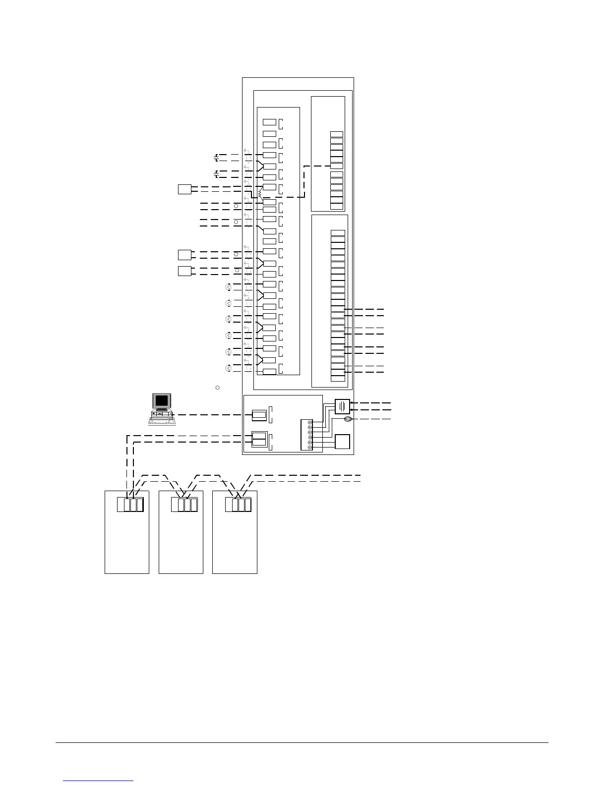
Figure 24. CSM Field Wiring Schematic
Chiller System Manager
Inputs
DI 4
DI 3
UI16
UI15
MicroTech II
Chiller #1
P8
LonCard
MicroTech II
Chiller #2
P8
Lon Card
MicroTech II
Chiller #3
P8
G
Lon Card
Lon Port
(Orange)
GBA
GBA A
To Additional chillers and/or
remote I/O modules
Notes:
1.
Except for the chilled water supply temperature sensor, all
inputs and outputs are optional.
2.
Using the LonWorks free topology network means
that “nodes” (chillers and remote I/O modules) can
be configured in bus, ring, star, or a combination of
these three network configurations.
3. LonWorks cable lengths are dependent on singly
or doubly terminated networks. Refer to Echelon’s
LonWorks FTT-10A Transceiver User’s Guide.
Ethernet network to PC with Internet Explorer
to run CSM User Interface and/or BAS
B
Cat 5 Ethernet Cable
Ethernet Port
(RJ45)
4.
Lon network cables to be run in shielding conduit
and must not be run near power wiring.
G
DI 2
Chilled Water Reset Override
UI14
UI13
DI 1
External Start/Stop
G
External Demand Limit
Relative Humidity
AI 12
AI 11
UI12
UI11
RH
-
+
499 Ω R
G
Spare
External Chilled Water Reset
UI9
AI 9
UI10
AI 10
G
DPT
UI8
AI 8
Loop Differential Press
Flow Meter
FM
2-10Vdc or 4-20mA
UI7
AI 7
2-10Vdc or 4-20mA
G
UI6
AI 6
Decoupler Line Temperature
UI5
AI 5
Outside Air Temperature
G
UI4
AI 4
Entering Condensor Water Temperature
UI3
AI 3
Leaving Condensor Water Temperature
G
UI2
AI 2
Chilled Water Return Temperature
UI1
AI 1
Chilled Water Supply Temperature
G
4-20 mA
0-10Vdc or 4-20mA
0-10Vdc or 4-20mA
GROUND
120 Vac (Model MTII-UC-1-CSM)
or
240 Vac (Model MTII-UC-2-CSM)
50/60 Hz
power source
Transformer
Battery
Black
Six
Position
Power
Connector
B-
B+
EGD
X2
CT
X1
Red
RED
BLK
GRN
GRN
Y/G
GRN
Outputs
NO8
C8
NC8
NO7
C7
NC7
NO6
C6
NC6
DO 8
DO 7
DO 6
NO5
C5
NC5
NO4
C4
NC4
NO3
C3
NC3
NO2
C2
NC2
NO1
C1
NC1
DO 5
DO 4
DO 3
DO 2
DO 1
Onboard
Power
Source
20 Vdc @ 80 mA
GND
-----
-----
------
------
AV+
GND
-----
-----
-----
-----
AV+
CSM Main Board
CSM Onboard I/O
5.
If a 4-20 mA signal is sent from the sensor, a 499
ohm resister is required across the Analog Input.
5
5
5
5
Alarm Horn
Alarm LED
2A @ 24V
2A @ 24V
Alarm Output
2A @ 24V
CSM On/Off
2A @ 24V
6.
BACnet IP or BACnet Ethernet BAS interface
standard. Interface to Modbus RTU BAS requires
optional driver.
6
CD 112024501
 Loading...


