IM-738 Page 25
Lifting Points
To determine the required lifting cable lengths and whether
four-or six-point lifting is required, use Table 5 & Table 6 and
Figure 25 & Figure 26.
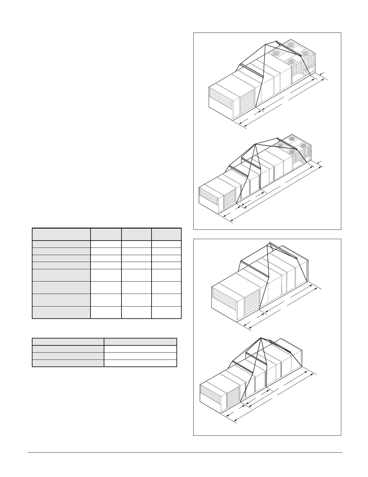
Referring to Figure 25 & Figure 26, note that dimension A is
the distance between the outer lifting points. The four outer
rigging cables must be equal to or longer than dimension A.
Dimension B shows the minimum distance between the outer
and the inner lifting points for six-point lifting. This can be
used to roughly determine the required length of the middle
cables for six-point lifting. Dimension A can be determined by
subtracting dimensions X and Y from dimension Z.
(i.e., A = Z- X-Y).
Where:
Z =Total unit length in inches
(refer to certified drawings for this dimension).
X =Outdoor/return air section length
(refer to Table 5 for this dimension).
Y = Refer to Table 6 for this dimension
(see Figure 25 & Figure 26).
If A ≤ 288" (7315 mm), 4-point lifting is sufficient.
If A > 288" (7315 mm), 6-point lifting is required.
Table 5: "X" Dimension (see Figure 25 & Figure 26)
Table 6: "Y" Dimension (see Figure 25 & Figure 26)
Figure 25. Unit Type RPS/RDT Lifting Points
Figure 26. Unit type RFS Lifting Points
OUTDOOR/RETURN AIR
SECTION
015C-030C 036C & 040C 045C & 075C
100 O.A. 000
PLENUM 40” (1016 mm) 52” (1321 mm) 48” (1259 mm)
0-30% O.A. 40" (1016 mm) 52" (1321 mm) 48” (1259 mm)
0-100% ECONOMIZER 40” (1016 mm) 52” (1321 mm) 72” (1829 mm)
0-100% ECONOMIZER
WITH 15” RETURN FAN
62” (1575 mm) — —
0-100% ECONOMIZER
WITH 30” RETURN FAN
52” (1321 mm) 52” (1321 mm) —
0-100% ECONOMIZER
WITH 40” RETURN FAN
— 80” (2032 mm) —
0-100% ECONOMIZER
WITH 44” RETURN FAN
— — 72” (1829 mm)
RPS UNIT SIZE DIMENSION ‘Y”
015C — 030C 49.5" (1257 mm)
036C & 040C 38.2” (970 mm)
045C — 075C 39.5” (1003 mm)
A
Z
X
Y
4 L i f t i n g P o i n t s
X
Y
6 L i f t i n g P o i n t s
B
A
0 1 5 C 0 3 0 C : N M i n . = 6 2 " ( 1 5 7 5 m m )
0 3 6 C 0 4 0 C : B M i n . = 8 4 " ( 2 1 3 4 m m )
0 4 5 C 0 7 5 C : B M i n . = 7 2 "
1 8 2 9 m m
A
Z
X
4 L i f t i n g P o i n t s
Y = 0
X
6 L i f t i n g P o i n t s
B
A
0 1 5 C 0 3 0 C : N M i n . = 6 2 " ( 1 5 7 5 m m
0 3 6 C 0 4 0 C : B M i n . = 8 4 " ( 2 1 3 4 m m )
0 4 5 C 0 7 5 C : B M i n . = 9 6 " ( 2 5 2 9 m m )
Z
Y = 0