IOMM Starter 21
Description
Controlled
Stop
Auto
Reset
60 Thermistor Trip (on DIN#1) N N
61 Stack OT Switch Trip (on DIN#2) N N
71 Analog Input Trip Y Y
82 Modbus Timeout Y Y
94 CPU Error – Software Fault N N
95 CPU Error – Parameter Storage Fault N N
96 CPU Error – Illegal Instruction Trap N N
97 CPU Error – Software Watchdog Fault N N
98 CPU Error – Spurious Interrupt N N
99 CPU Error – Program Storage Fault N N
• If a fault occurs that has a Y in the “Controlled Stop” column, and P21 (Controlled Fault
Stop) is set to On, and P9 (Stop Mode) is set to dcL, then the starter will perform a voltage
decel to stop. Otherwise it will coast to stop.
• If a fault occurs that has a Y in the “Auto Reset” column, and P22 (Auto Fault Reset
Time) is set to some value other than OFF, then the fault will automatically be cleared
after the time specified by P22.
Low Voltage Wye-Delta (LVYD
Operation
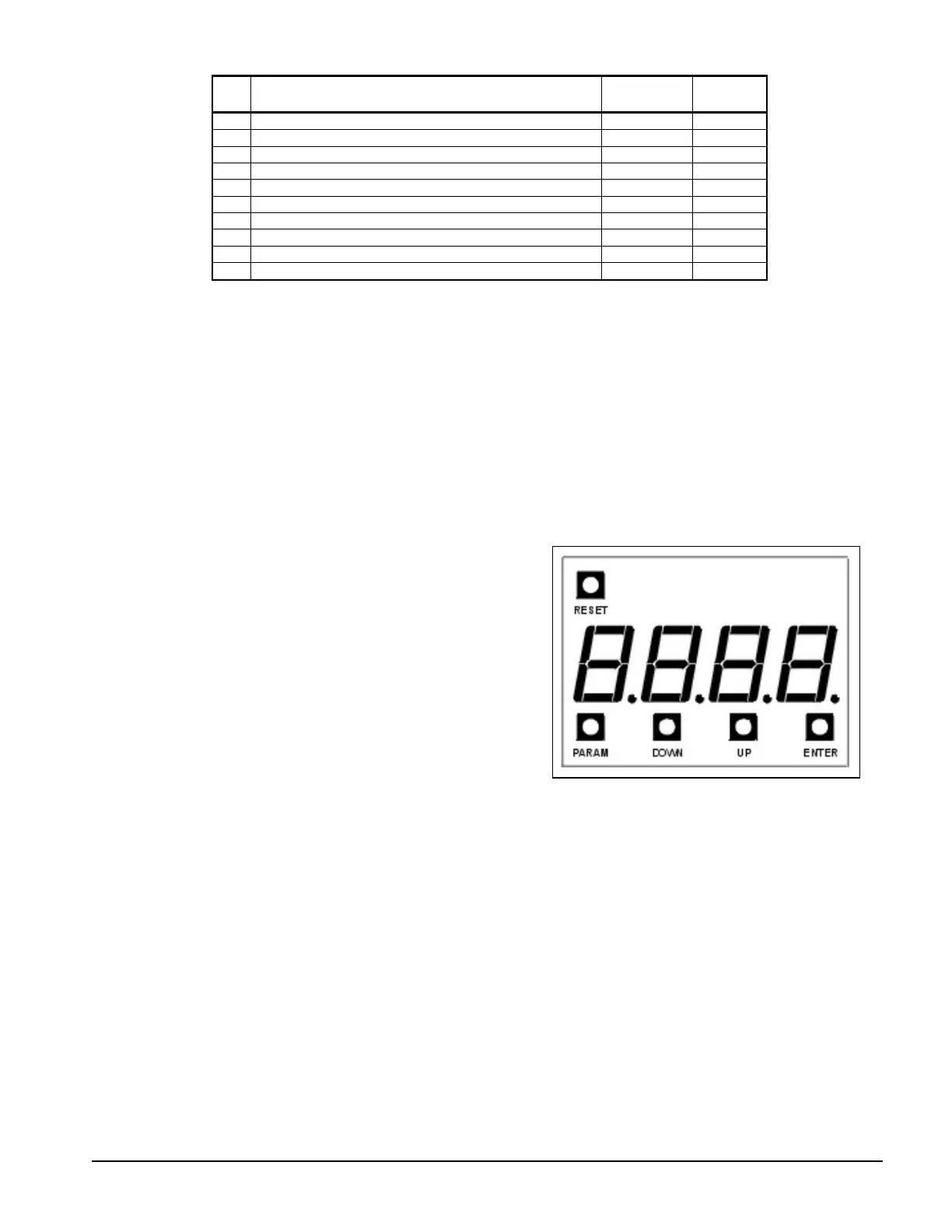
• LED Display
• View parameters, messages and faults.
• Shows software revision on power up.
Programming·
• Press PARAM to enter the menu and then UP
or DOWN to reach the desired parameter.
• Press ENTER to show the present value of the
parameter.
• Press UP or DOWN to change the parameter value.
• Press ENTER to store the new value or PARAM to abandon the change.
Quick Meters·
• Press DOWN to display the motor thermal overload content.
• Press UP to display the incoming line phase order.
• Press ENTER to display the status meter.
Fault Log
• Select P24 and press ENTER. The most recent fault will be displayed as “xFyy” where x
will be 1 to indicate the most recent fault is being displayed and yy is the fault code.
• Press DOWN to view older faults. Up to 9 faults may be stored in the log.
 Loading...


