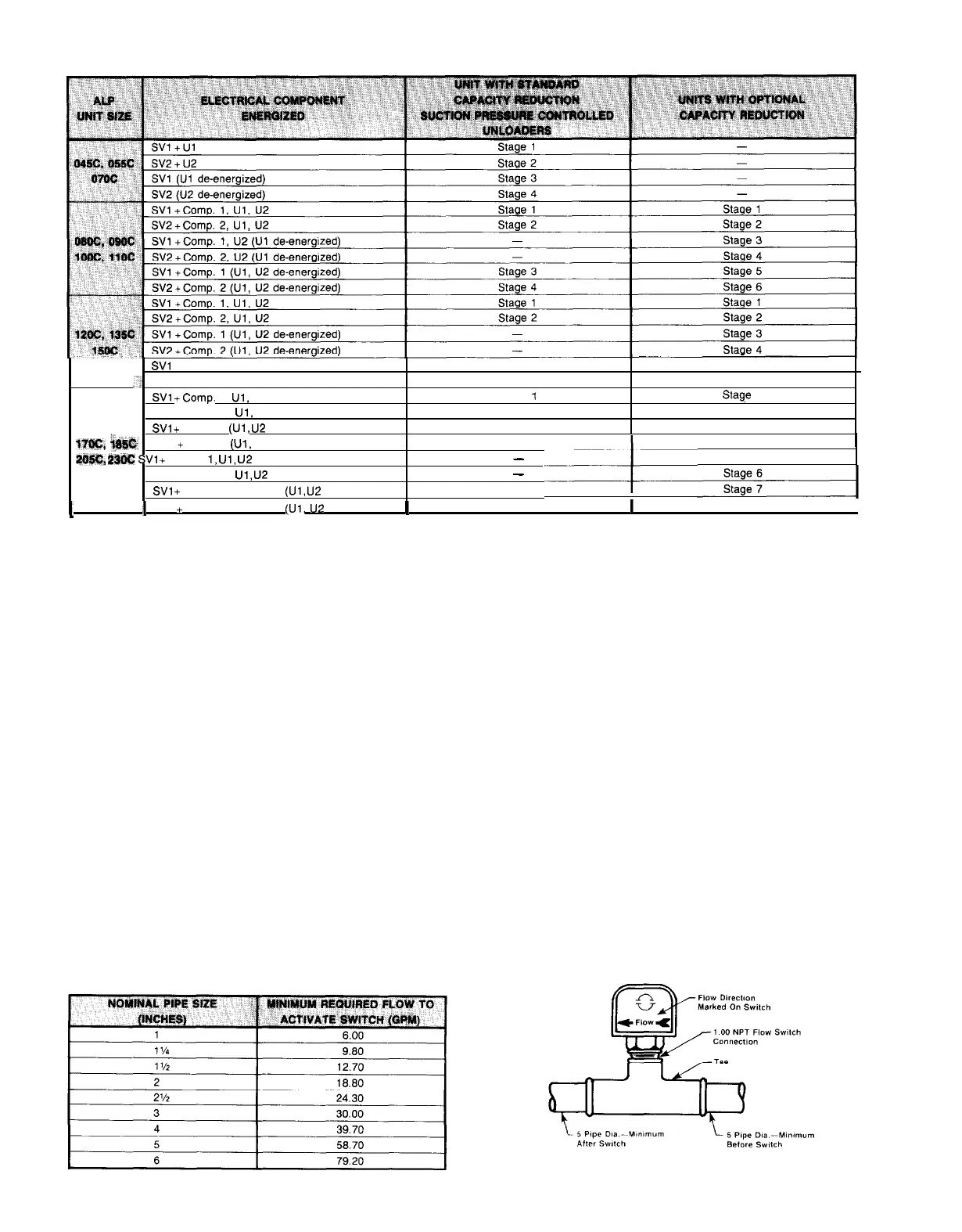
Table 18. Capacity reduction
SVl + Comp. 1 + Comp. 3 (R3 energized)
,‘:
SV2 + Comp. 2 + Comp. 4 (R4 energized)
SW
+Comp. 1,
Ul.
U2
SV2 + Comp. 2,
Ul,
U2
SVI
+
Comp. 1
(Ul,
U2
de-energized)
t7lac,
i
SV2
+
Comp. 2
(Ul,
U2 de-energized)
a?$#!&
m
SVl
+
Comp.
1,
Ul,
U2
+ Comp. 3 (R3 energized)
SV2 + Comp. 2,
Ul,
U2
+ Comp. 4 (R4 energized)
SVl
+
Comp. 1 + Comp. 3
(Ul,
U2
de-energized)
Stage 3
Stage 5
Stage 4
Stage 6
Stage
1
Stag-e
1
Stage 2
Stage 2
Stage 3
Stage 3
Stage 4
_I
Stage 4
-
..-_I
Stage 5
-
Stage 5
--
1
1
SV2
+
Comp.
2
+
Comp.4
(Ul,
UZ
Stage
6
Stage
6
de-energized)
1
I
I
NOTES:
1.
Compressor staging for units with suction pressure controlled unloaders and unloaders controlled from a remote source
(discharge
air, return water, etc.) is the same.
2. See page 54 for more information on unloaders controlled from suction pressure.
WATER PIPING FOR CHILLED WATER APPLICATIONS
Due to the variety of piping practices, it is advisable to follow the recommendations of local
authorities. They can supply the installer with the proper building and safety codes required
for a safe and proper installation.
FLOW SWITCH FOR CHILLED WATER APPLICATIONS
A WATER FLOW SWITCH MUST BE MOUNTED in either
the entering or leaving water line to insure that there will be
adequate water flow and cooling load to the evaporator before
the unit can start. This will safeguard against slugging the
compressors on startup. It also serves to shut down the unit
in the event that water flow is interrupted to guard against
evaporator freeze-up.
A flow switch is available from McQuay under ordering
number
860-175033B-00.
It is a “paddle” type switch and
adaptable to any pipe size from 1” to 6” nominal. Certain
Table 19. Flow switch minimum flow rates
Figure 13.
Page 18 /
IM
269
minimum flow rates are required to close the switch and are
listed in Table 18. Installation should be as shown in Figure
13.
Electrical connections in the unit control center should be
made at terminals 5 and 6. The normally open contacts of
the flow switch should be wired between these two terminals.
There is also a set of normally closed contacts on the switch
that could be used
for an indicator light or an alarm to in-
dicate when a “no
flow” condition exists.
 Loading...