LOCATION
Care should be taken in the location of the unit to provide
Minimum clearances as shown in Figure 3 will prevent most
proper airflow to the condenser, minimizing effects on
con-
discharge air recirculation to the condenser which will have
densing pressure.
a significant effect on unit performance.
SERVICE ACCESS
Each end of the unit must be accessible after installation for
periodic service work. Compressors, filter-driers, and manual
liquid line shutoff valves are accessible on each side of the
unit adjacent to the control box. High pressure, low pressure,
and motor protector controls are on the compressor. Most
other operational, safety and starting controls are located in
the unit control box.
On all ALP units the condenser fans and motors can be
removed from the top of the unit. A complete fan/motor
assembly should be removed for service.
CAUTION: Disconnect all power to unit while servicing
con-
denser fan motors.
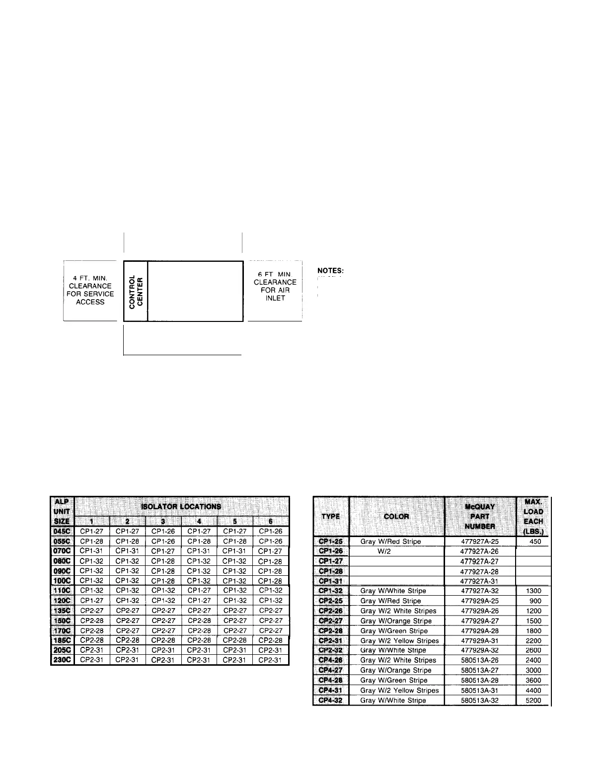
Figure 3. Clearance Requirements
ALP-045C
thru 230C
6 FT. MIN. CLEARANCE
FOR AIR INLET
(1) Minimum clearance between units is 12 feet.
(2) Units must not be Installed in a pit that is deeper than the height of the unit.
(3) Minimum clearance on each side is 12 feet when installed in a pit.
6 FT. MIN. CLEARANCE
FOR AIR INLET
VIBRATION ISOLATORS
Vibration isolators are recommended for all roof mounted in-
stallations or wherever vibration transmission is a considera-
tion. Table 1 lists spring isolators for all ALP unit sizes. Figure
4 shows isolator locations in relation to the unit control center.
Figure 5 gives dimensions that are required to secure each
Table 1. Vibration Isolators (Spring)
Q?txJ
CPl-31 CPl-31
CPl-27 CPl-31 CPl-31
CPl-27
ioU@
CPl-32
CPl-32
CPl-28 CPl-32
CPl-32
CPl-28
OS@
CPl-32 CPl-32
CPl-28 CPl-32 CPl-32
CPl-28
low
CPl-32 CPl-32
CPl-28 CPl-32 CPl-32
CPl-28
?8W:
CP2-28
CP2-26
CP2-28 CP2-26 CP2-28
CP2-28
Z96Q
CP2-31
CP2-31
CP2-31
CP2-31
CP2-31
CP2-31
OgoC
CP2-31 CP2-31
CP2-31 CP2-31 CP2-31 CP2-31
McQuay isolator selection to the mounting surface. Table 3
shows the isolator loads at each location shown in Figure 4,
and the maximum loads for each McQuay selection are
shown in Table 2.
Table 2. Spring-flex Isolators
Gray
W/2
White Stripes
Gray W/Orange Stripe
Gray W/Green Stripe
Gray W/2 Yellow Stripes
477927A-26
600
477927A-27
750
477927A-26
900
477927A-31
1100
Page 4
/
IM 269
 Loading...