INTRODUCTION
GENERAL DESCRIPTION
McQuay type ALP SEASONCON air cooled condensing units
are designed for outdoor installations and are compatible with
either air handling or chilled water systems. Each unit is
com-
pletely assembled and factory wired before evacuation, charg-
ing and testing, and comes complete and ready for installa-
tion. Each unit consists of twin air cooled condensers with
integral subcooler sections, multiple accessible hermetic
com-
pressors, complete discharge piping and suction connections
for connection to any air or water cooling evaporator.
The electrical control center includes all safety and
operating controls necessary for dependable automatic
operation except for the cooling thermostat since this is
somewhat dependent on the unit application. Condenser fan
motors are fused in all three conductor legs and started by
their own three-pole contactors. Compressors are not fused
but may be protected by optional circuit breakers, or by field
installed fused disconnect.
NOMENCLATURE
A L P
-
080 C
T
CESIGN
;/II’-~‘h*:,.;r
NOMINAL CAPACITY (TONS)
INSPECTION
When the equipment is received, all items should be carefully
be checked before unloading the unit
to
ba sure that it agrees
checked against the bill of lading to insure a complete ship- with the power supply available. Physical damage to unit after
ment. All units should be carefully inspected for damage upon
acceptance is not the responsibility of
McQuay.
arrival. All shipping damage should be reported to the
car-
NOTE: Unit shipping and operating
weights
are available
rier and a claim should be filed. The unit serial plate should
in the physical data tables on pages 10 and
1
1.
INSTALLATION
NOTE: Installation and maintenance are to be performed only by qualified personnel who are familiar with local codes
and regulations, and experienced with this type of equipment. CAUTION: Sharp edges and coil surfaces are a potential
injury hazard. Avoid contact with them.
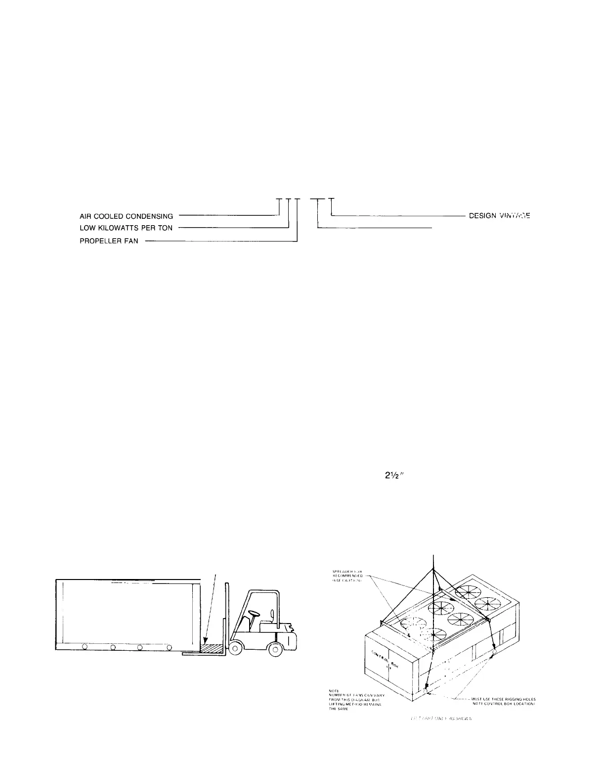
HANDLING
Care should be taken to avoid rough handling or shock due
to dropping the unit. Do not push or puli the unit from anything
other than the base, and block the pushing vehicle away from
the unit to prevent damage to the sheetmetal cabinet and end
frame (see Figure 1).
Never allow any part of the unit to fall during unloading or
Figure
1.
Suggested Pushing Arrangement
BLOCKING REQ’D.
ACROSS FULL WIDTH
I
i
n
moving as this may result in serious damage.
To lift the unit,
2%”
diameter lifting holes are provided in
the base of the unit. Spreader bars and cables should be ar-
ranged to prevent damage to the condenser coils or unit
cabinet (see Figure 2).
Figure 2. Suggested Lifting Arrangement
IM 269 I Page 3
 Loading...