EVAPORATOR FAN INTERLOCK FOR AIR HANDLER COIL INSTALLATIONS
It is important to interlock the air handler evaporator fan with
the condensing unit control to insure that there will be a
cool-
purpose. Remove the jumpers between terminals 111 and
11.2 for circuit 1 and 211 and 212 for circuit 2. Use these ter-
ing load on the evaporator before the unit can start to
pre-
minals for the evaporator fan interlock contacts. Be sure to
vent compressor slugging. A pair of terminals for each
refrigerant circuit is available in the unit control center for this
keep circuits separate by using two contacts on dual circuit
machines.
UNIT LAYOUT
&
PRINCIPLES OF OPERATION
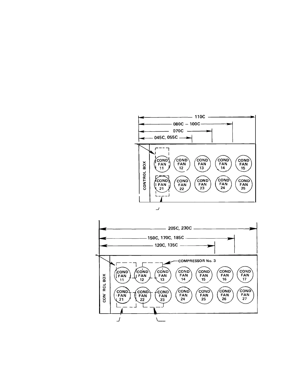
Figure 14. Major Component Locations
The figures below illustrate component locations within the unit for each unit size.
COMPRESSOR No. 1
-
COMPRESSOR No. 1
I
I
L---J
COMPRESSOR No. 2
-/
TOP VIEW OF UNIT
COMPRESSOR No. 2
J
\_
COMPRESSOR No. 4
CONTROLCENTER
All electrical controls are enclosed in a weatherproof control
center with keylocked, hinged access doors. The control
center is composed of two separate compartments, line
voltage and control voltage. All of the line voltage
com-
ponents, except for the input terminals of the PVM, are
located in the compartment on the right side of the unit. The
control voltage components are located on the left side with
the live terminals located behind a deadfront panel. This
pro-
tects service personnel from live terminals when accessing
the adjustable and resettable controls.
IM 269 I Page
19
 Loading...