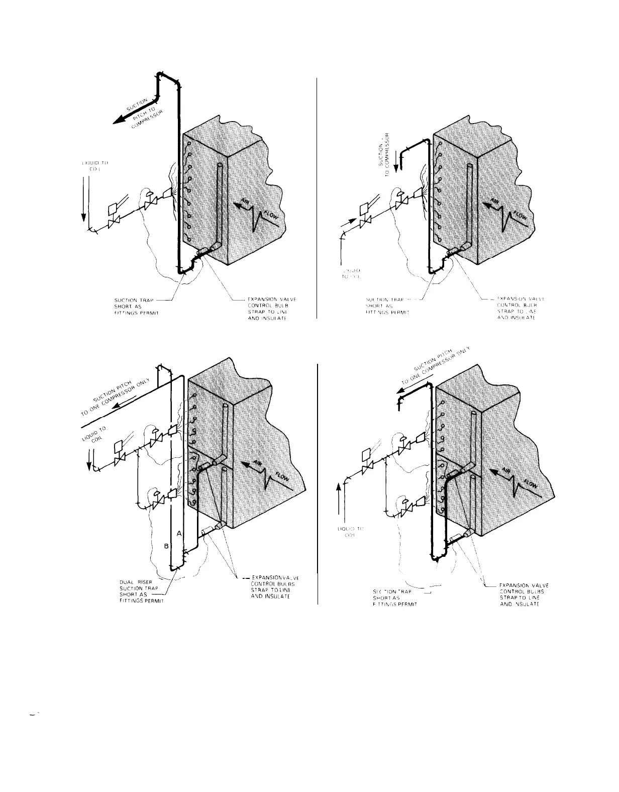
Figure 6. SINGLE CIRCUIT EVAPORATOR
-
RECOMMENDED PIPING
If Row Split Coils Are Used, Duplicate The Piping
CONDENSING UNIT ABOVE THE EVAPORATOR
CONDENSING UNIT BELOW THE EVAPORATOR
Figure 7. DUAL CIRCUIT EVAPORATOR (FACE SPLIT)
-
RECOMMENDED PIPING
_d”
\
_,
D”Ai
RISER
L
-.-
1
~~
iVP4NSlON
Lla.,vt
;:
CONTROL
BULBS
SUCTION
TRAP
L
FXPANSlOlv
VALVE
‘S~FIPIV
TO
LlNt
\.__
_--
SHORT
AS
$1
!
-,m
.R‘iP
-
TONTROL BLLRS
--
i’
“IUD
INSULnrE
FITTINGS
PERMIT
SMORT
*s
STRAP
TO
LlhE
F
TT,rvi,S
PFPMll
4ND
US”L4TE
NOTES:
1.
Piping shown is for one compressor circuit; second circuit is similar. Must have separate piping for each compressor circuit.
2.
Trap for double suction riser should be as small in horizontal direction as fittings will allow.
3.
The thermal expansion valve equalizer line should be placed just past the thermal sensing bulb on the side or top of the pipe.
4. A separate expansion valve is required for each distributor and mounted per manufacturer’s recommendations.
(See additional notes under recommended line sizes, Table 7.)
REFRIGERANT PIPING CONNECTIONS
Refrigerant piping connections will be made at the
com-
unit. When piping, allow room for the unit disconnect and field
pressor end of the unit. Suction and liquid lines should be
wiring to the unit. Figures 8 and 9 show piping connections
routed through the compressor enclosure on each side of the
and sizes for each ALP model.
IM 269
/ Page 7
 Loading...