PHASE/VOLTAGE MONITOR (OPTIONAL)
tection
against three-phase electrical motor
loss due
to power
failure conditions, phase loss, and phase reversal. Whenever
any of these conditions occur, an output relay is deactivated,
disconnecting power to the thermostatic control circuit,
automatically pumping down the unit.
The phase/voltage monitor is a device which provides
pro-
put relav does not close. oerform the followina tests.
i.
2.
Check the voltages between Ll-L2,
L1-L3-and
L2-L3.
These voltages should be approximately equal and within
+ 10% of the rated three-phase line-to-line voltage.
If these voltages are extremely low or widely unbalanced
check the power system to determine the cause of the
problem.
The output relay remains deactivated until power line con-
ditions return to an acceptable level. Trip and reset delays
have been provided to prevent nuisance tripping due to rapid
power fluctuations.
3.
When three-phase power has been applied, the output relay
should close and the “run light” should come on. If the
out-
If the voltages are good, turn off the power and interchange
any two of the supply power leads at the disconnect.
This may be necessary as the phase/voltage monitor
is sensitive to phase reversal. Turn on the power. The out-
put relay should now close after the appropriate delay.
HOT GAS BYPASS (OPTIONAL)
Hot gas bypass is a system for maintaining evaporator
pressure at or above a minimum value. The purpose for do-
ing this is to keep the velocity of the refrigerant as it passes
through the evaporator high enough for proper oil return to
the compressor when cooling load conditions are light. It also
maintains continuous operation of the chiller at light load con-
ditions. Hot gas bypass kits are described on page 9.
The solenoid valve should be wired to open whenever the
unit thermostat calls for the first stage of cooling (see Figures
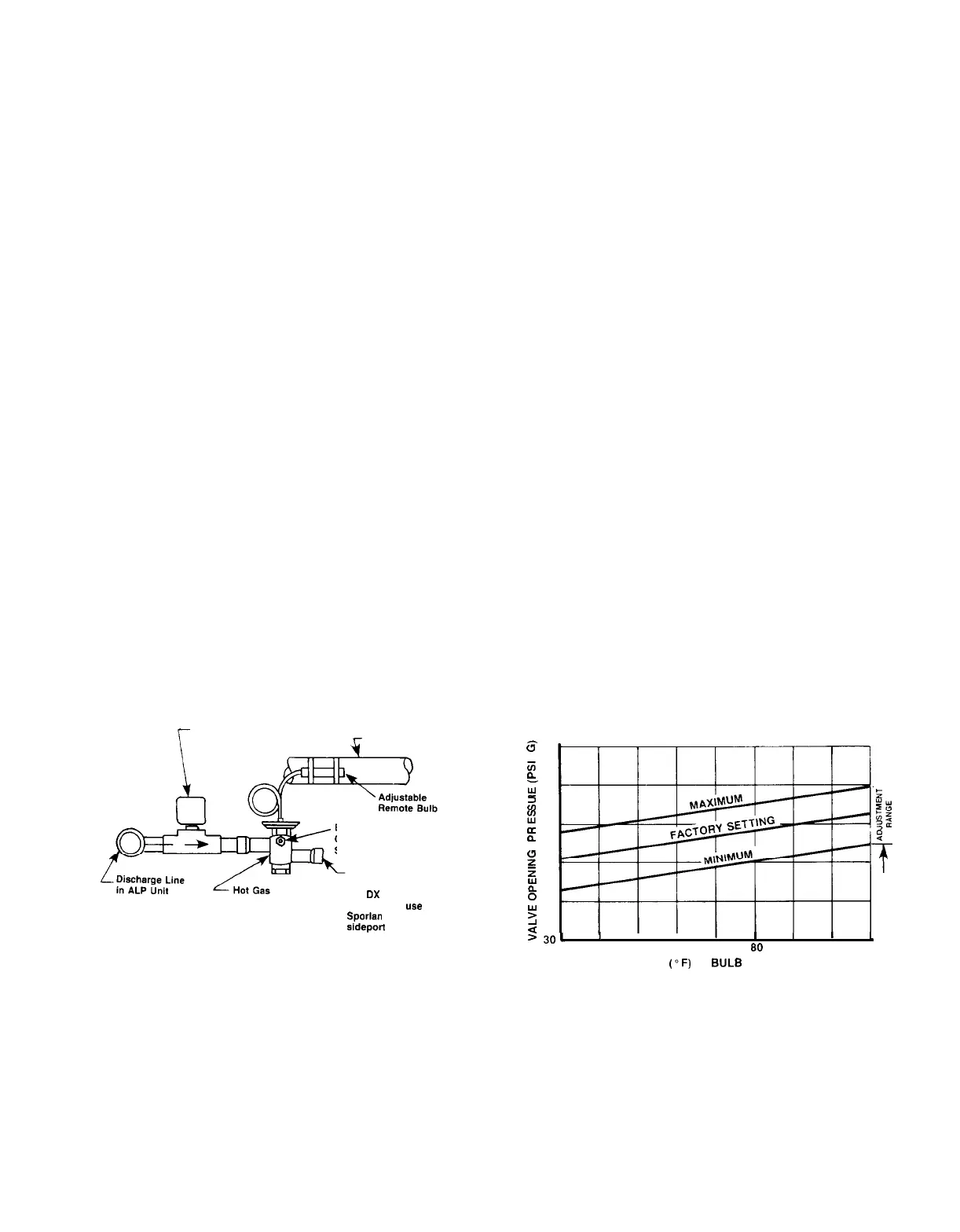
10 thru 12). The pressure regulating valve that
McQuay of-
fers is factory set to begin opening at 58 psig (32F for R-22)
when the air charged bulb is in an 80F ambient temperature.
The bulb can be mounted anywhere as long as it senses a
fairly constant temperature at various load conditions. The
compressor suction line is one such mounting location. It is
generally in the 50F to 60F range. The chart below indicates
that when the bulb is sensing 50F to 60F temperatures, the
valve will begin opening at 54 to 56 psig. This setting can
be changed as indicated above, by changing the pressure
of the air charge in the adjustable bulb. To raise the pressure
setting, remove the cap on the bulb and turn the adjustment
Hot Gas Bypass Piping Diagram
Hot Gas Bypass
Solenoid Valve
4
Suction Line
External Equalizer
Connection to Suction
Side of Evaporator
To Evaporator Inlet
After Expansion Valve
Bypass Valve
(On
OX
coils with
distributors,
use
Sporlan auxiliary
sideport connector
or equivalent)
screw clockwise. To lower the setting, turn the screw
counterclockwise. Do not force the adjustment beyond the
range it is designed for, as this will damage the adjustment
assembly.
The regulating valve opening point can be determined by
slowly reducing the system load (or increasing the required
chilled water temperature setting indicated on the unit ther-
mostat), while observing the suction pressure. When the
bypass valve starts to open, the refrigerant line on the
evaporator side of the valve will begin to feel warm to the
touch.
CAUTION: The hot gas line may become hot enough
to
cause
injury in a very short time, so care should be taken during
valve checkout.
On installations where the condensing unit is remote from
the evaporator, it is recommended that the hot gas bypass
valve be mounted near the condensing uni! to minimize the
amount of refrigerant that will condense in the hot gas line
during periods when hot gas bypass is not required.
Hot Gas Bypass Adjustment Range
REMOTE BULB ADJUSTMENT RANGE
6
80
z
P
$
70
4
z
2
Jg
z
60
Z$
?a
E
2
P
50
z
f
2
O
2
40
ti
>
301
I
I I
I
I
I
30
40 50 60 70
SO
90 100 110
TEMP.
(OF)
AT
BULB
LOCATION
IM 269
/
Page 55
 Loading...