APPENDIX
OPTIONAL CONTROLS
SPEEDTROL HEAD PRESSURE CONTROL (OPTIONAL)
The SPEEDTROL system of head pressure control operates
partments. Units with 460 volt power have a transformer
in conjunction with FANTROL by modulating the motor speed
mounted inside the condenser fan 21 fan compartment to step
on fans 11 and 21 in response to condensing temperature.
the voltage down to 230 volts for the SPEEDTROL motors.
By reducing the speed of the last fan as the condensing
The SPEEDTROL control starts to modulate the motor
pressure falls, the unit can operate at lower ambient
speed at approximately 105°F and maintains a minimum
con-
temperatures.
densing pressure of 170 to 180 psig.
The SPEEDTROL fan motor is a single phase, 2081240 volt,
The SPEEDTROL sensors are clipped to a return bend on
thermally protected motor specially designed for variable
the bottom row of the condenser coil. SPEEDTROL controls
speed application. The solid-state speed controls SC1 1 and
and SPEEDTROL transformer are shown in Figures 21 and
SC21 are mounted inside condenser fan 11 and 21 fan
com-
23.
COMPRESSOR UNLOADERS (OPTIONAL)
UNLOADERS CONTROLLED FROM SUCTION PRESSURE:
With a decrease in load, the suction pressure drops, pressure
solenoid
U1
which increases the compressor capacity.
control PC8 closes, energizing unloader solenoid
U1.
This
closes the suction port to one cylinder bank and reduces the
PC8,
cut-in: 64 psig; cut-out: 72 psig
compressor capacity. Compressor circuit 2 operates the same
PC9,
cut-in: 64 psig; cut-out: 72 psig
way.
The cut-in and cut-out pressures can be adjusted to meet field
With an increase in the load, the suction pressure
in-
combinations. If the unloader cycles excessively, the
differen-
creases, pressure control PC8 opens, de-energizing unloader
tial between cut-in and cut-out should be increased.
LOW AMBIENT START (OPTIONAL)
Low ambient start is available on all units as an option with
FANTROL and included automatically with optional
SPEED-
TROL. It consists of a solid-state, normally closed time delay
wired in series with a relay. These are both wired in parallel
to the liquid line solenoid valve so that when the solenoid
valve is energized by the unit thermostat the low ambient start
relay is also energized through the time delay. The relay has
contacts that essentially short-circuit the low pressure
con-
trol and freezestat and allow the compressor to start with the
low pressure control open.
After about 2% minutes, the time delay will open and
de-
To check the control, turn off all power to the unit and
remove the wire(s) leading to the terminals of the low pressure
control(s)
LPl
and LP2. Remove power to the compressor
and jumper across terminals 48 to 50 for circuit 1 and 78 to
80 for circuit 2. Switch the
pumpdown
switch(es)
PS1
and
PS2 to the “auto pumpdown” position. Energize the control
circuit by turning on the control circuit disconnect or main
power disconnect (depending on the installation) and the con-
trol stop switch
S1
The compressor contactors should pull
in instantly and trip back out after the 2% minute time delay.
energize the relay. If the system has not built up enough
evaporator pressure to close the low pressure control, the
compressor will stop. The time delay can be reset to its
original normally closed position by moving the
pumpdown
switch(es)
PS1
or PS2 to the “manual pumpdown” position.
Moving the
pumpdown
switch back to the “auto pumpdown”
position will again energize the relay for another attempt at
startup. If the system has built up enough evaporator pres-
sure, the compressor will continue to run.
Low Ambient
Low Ambient
Start
Time
Delay
start Relay
0
NOTE: Line is only hot when the unit thermostat calls for compressor to run.
HIGH AMBIENT (OPTIONAL)
The high ambient control is a single pole pressure activated
switch that closes on a pressure rise to partially unload one
or both circuits. It senses condenser pressure and is factory
set to close at 375 psig and will automatically reset at 300
psig. To check the control, either block off condenser sur-
face or start the unit with fuses in only one condenser fan
fuse block (FB6) and observe the cut-in point of the control
by monitoring when the compressor unloads. The purpose
of the control is to allow the unit to continue operating when
the ambient temperature exceeds the design temperature of
the unit. High ambient sensor locations are shown in Figures
20 and 22.
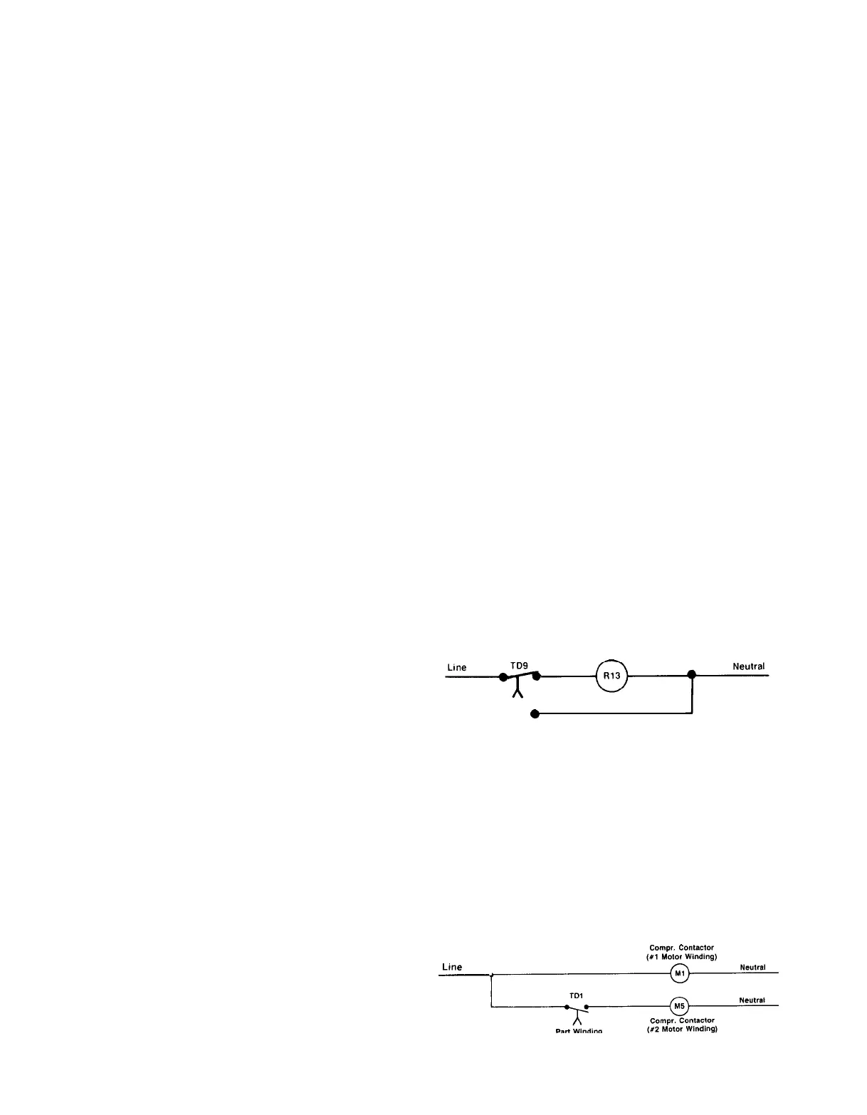
PART WINDING START (OPTIONAL)
Part winding start is available on all voltage units and con-
sists of a solid-state time delay wired in series with the
con-
tactor that energizes the second winding of each compressor
motor. Its purpose is to limit current in-rush to the com-
pressors upon startup. As each compressor starts, the
con-
tactor of the first motor winding is delayed for 1 second.
Control checkout is best accomplished by observation as
each contactor is pulled in to see that the 1 second delay
occurs before the second contactor pulls in.
Page 54 / IM 269
-
Line
I?--
Part
Winding
Time Delay
 Loading...