HIGH PRESSURE CONTROL
The high pressure control is a single pole pressure activated
trol on a high pressure gauge.
switch that closes on a pressure rise. When the switch closes,
The control is attached to a Shrader fitting and is located
R1
is energized which in turn de-energizes the control cir-
on a cylinder head near the discharge King valve. CAUTION:
cuit,
shutting down the compressor circuit. R1 also locks itself
Although there is an additional pressure relief device in the
in a manually resettable holding circuit through
RS1.
The
system set at 450 psig, it is highly recommended
that
the
switch is factory set to close at 400 psig and open at 300 psig.
“control stop” switch
S1
be close
at
hand in case the high
To check the control, either block off condenser surface pressure control should malfunction.
or start the unit with condenser fan motor fuses in only one
After testing the high pressure control, check the pressure
fan fuse block (FB6) and observe the cutout point of the
con-
relief device (on the condenser header) for leaks.
LOW PRESSURE CONTROL
The low pressure control is a single pole pressure switch that lowest evaporator pressure reached before cutout is the
closes on a pressure rise. It senses evaporator pressure and
cutout setting of the control. Wait for the compressor lockout
is factory set to close at 60 psig and automatically open at
time delays
TD1
and TD2 to time out. By moving the
pump-
25 psig. The control has an adjustable range of 20 inches down
switch(es)
PSI and PS2 to the “auto pumpdown”
posi-
of Hg. to 100 psig and an adjustable differential of 6 to 40 tion, evaporator pressure will rise. The highest evaporator
psig. To check the control (unit must be running), move the
pressure reached before compressor restart is the cut-in
set-
pumpdown
switch(es)
PS1
and PS2 to the “manual
pump-
ting of the control.
down” position. As the compressor pumps down, condenser
The control is attached to a Shrader fitting and is located
pressure will rise and evaporator pressure will drop. The below the suction King valve body.
FANTROL HEAD PRESSURE CONTROL
FANTROL is a method of head pressure control which
automatically cycles the condenser fans in response to
con-
denser pressure and ambient air temperature. This maintains
head pressure and allows the unit to run at low ambient air
temperatures.
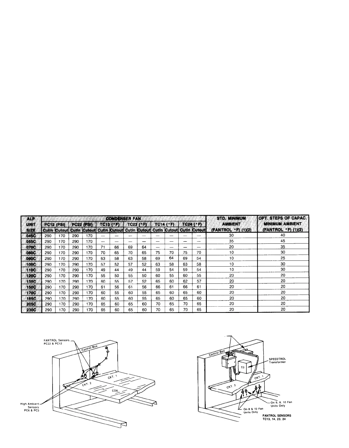
All ALP units have dual independent circuits with the fans
for circuit 1 and circuit 2 being controlled independently by
the condensing pressure and ambient air of each circuit. Fans
Table 23. Factory FANTROL Settings
11 and 21 start with each compressor and fans 12 and 22
cycle on and off in response to condenser pressure. The
cut-
out and cut-in pressures are given in Table 23. Fans 13 and
14 (circuit 1) and fans 23 and 24 (circuit 2) are
con-
trolled by ambient temperature and are factory set at the
values given in Table 23. Note that the number of fans on
each unit varies. FANTROL sensor locations are shown in
Figures 20 thru 23.
NOTES:
(1) With SPEEDTROL, all units minimum ambient operating temperature drops to 0°F.
(2) Minimum head pressure on partly loaded compressor
is
110 psig; on full load it
is
170
psig.
Figure 20.
Figure 21.
SPEEDTROL
Controls
Page 52
/
IM 269
 Loading...