McQuay IM 672-3 15
Installation Guidelines
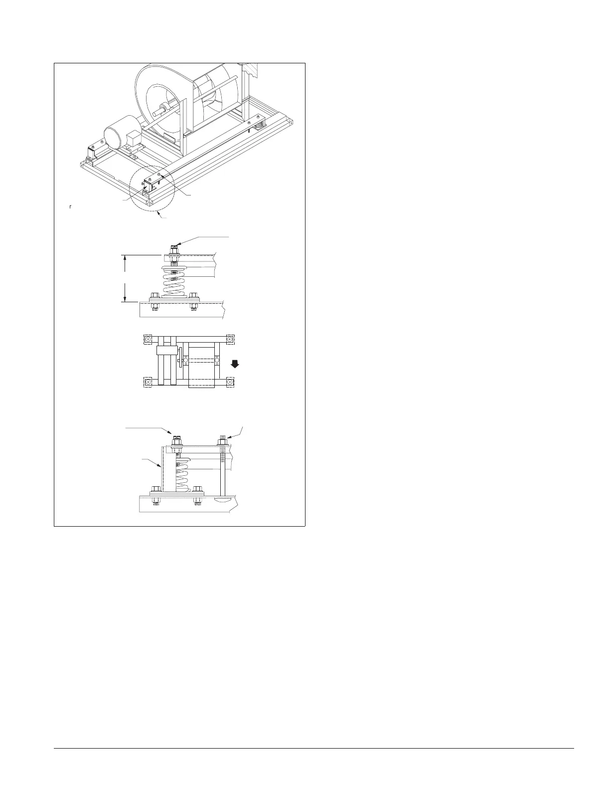
Figure 26: Removing shipping brackets
Electrical Installation
• Electrical service to the fan must correspond to the rated
voltage on the motor nameplate and conform to the National
Electric Code and local restrictions.
• Connect the fan section metal frame to the building
electrical ground.
• A door electrical interlock is not provided as standard.
• Thermal motor protection is external to the unit. Unless the
unit is provided with a variable frequency drive (VFD) or a
unit mounted starter, thermal protection and a disconnect
switch provision per electric codes are provided by others.
• When the unit is factory provided with a disconnect switch,
starter or a variable frequency drive (VFD), the components
are mounted on the outside of the unit cabinet. Factory
wiring is provided from the device to the unit internal motor.
M o t o r
F a n
P O S 1
P O S 2
P O S 3
P O S 4
A i r f l o w
F a n i s o l a t o r p o s i t i o n n u m b e r s
D i m " H "
S p r i n g h e i g h t
a d j u s t m e n t s c r e w
S p r i n g h e i g h t
a d j u s t m e n t s c r e w
S h i p p i n g h o l d
d o w n s c r e w
S h i p p i n g
b r a c k e t
D e t a i l A
S h i p p i n g h o l d d o w n
r e m o v e a n d d i s c a r d
( T y p i c a l 4 p l a c e s )
S e e d e t a i l " A "
S h i p p i n g b r a c k e t
e m o v e a n d d i s c a r d
( T y p i c a l 4 p l a c e s )
Unit sizes 006 - 090
 Loading...


