28 McQuay IM 672-3
Service and Maintenance
3
Pull the frame channel out the side.
If any top panel fastens into the frame channel (when the
frame channel is 24" or wider in direction of air flow),
remove the fasteners in the top panel before pulling out the
channel.
Removing the Fan Section
The fan shaft, motor, and any drive components can be
removed and replaced through the access door opening. If
required, the side panel can be removed for additional access.
If fan replacement is required, the entire fan assembly can be
pulled out the side of the cabinet. The fan assembly includes
the fan housing, the bearing support, and the fan base.
To remove the fan assembly:
1
Remove the side panels and any intermediate supports
(follow instructions for side panel removal)
2 Once the panels and any intermediate supports are
removed, disconnect the neoprene bulk head seal that is
attached to the fan discharge
3 Remove the four discharge angles that hold the neoprene
canvas in place around the discharge opening
4 Disconnect the fan sled from each of the corner mounts and
pull the entire assembly out the side of the unit
5 After the fan sled is out, loosen the fan bearings and pull
out the shaft
6 Disconnect the fan housing from the fan sled, and bearing
support by removing the attaching bolts
7 Replace the new fan, reconnect the shaft and bearings and
put the fan assembly in the cabinet.
8 Replace panels and fasteners.
Removing and Replacing the Coil
The coil can be removed by the side, top, or a combination of
both. The size and configuration of the coil affects how the
coil can be removed. Single banks of coil are fastened only on
the connection side of the unit. Stacked and staggered coils are
fastened on both ends of the coil. See the instructions below
for details to remove each coil type.
Before removing the coil, disconnect all piping. The
instructions below assume the coil is mounted in a
sectionalized coil section where the frame channel can be
removed without affecting other components. If the coil
section is unitized with other components, removing the top
frame channel requires removing additional panels.
Removing Single Coils
Note – Single coils are bolted to the unit on the connection end.
The connection end is held in place with a clamp
.
1 Disconnect all piping and remove the brass plugs for the
vents and drains located in the connections.
2 Remove all screws and remove the access panel.
3 Remove the screws holding the coil in place.
4 Lift and pull the coil out the side.
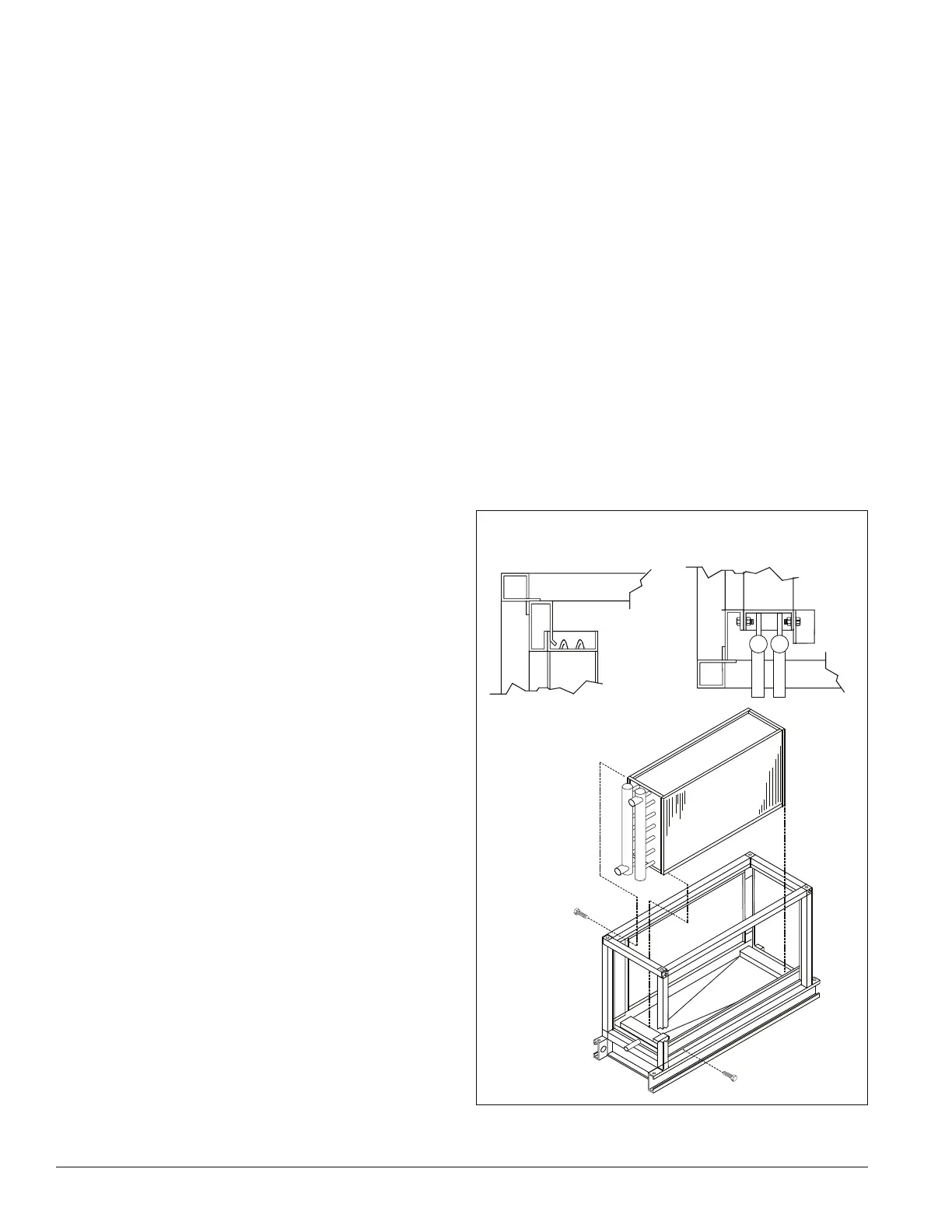
Installing Single Coils
1 Slide the coil through the opening in the coil section onto
the bottom coil rests.
2 To prevent any air bypass around the coil, place coils up
against the coil bulkheads. See Figure 44.
3 Once the coil is in place, fasten the coil to the section.
4 Caulk the seams between the coil casings and bulkheads.
See Figure 44.
5 If this is an additional coil being installed and not a
replacement, locate the coil supply and return connections
dimensionally. Carefully drill holes in the end panels of the
unit.
6 Remove the brass plugs for the vents and drains on the
connections.
7 Slip the panel over the connections.
8 Replace the brass plugs and panel fasteners.
Figure 44: Single coil removal
Coil
Connection
end
Coil
Opposite
connection
end
 Loading...


