"3072RT / 3772RT / 3772RT HD" Service & Parts Manual - ANSI Specifications March 2008
Page 2-7
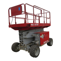
Emergency Stop
Emergency Stop
Lift / Drive
Speed / Torque
Choke / Glow Plug
Generator (Optional)
Horn (Optional)
Drive Enabled Indicator
(Optional)
Outrigger Extend/Retract
(Optional)
Hour Meter
Engine Start
(Green)
Engine
Start / Stop
Choke/Preheat
(Black)
Circuit Breaker
Gasoline/Propane (Dual Fuel)
Platform /
Chassis
Engine Stop
(Red)
Throttle
(Green)
Lower
(Green)
Raise
(Green)
ALARMS AND SWITCHES
Emergency Stop Button
There are two red emergency stop
buttons: one located on the platform
control console and the other on the
base control panel. This stop button,
when in the “OUT” (ON) position, provides
power to the desired control station. Also,
the stop button, in the event of an emer-
gency can be used to turn off the power
by pushing “IN” (OFF). All functions stop
immediately when depressed.
Turn the button clockwise to reset.
NOTE: As a safety feature, selecting
and operating the base controls will
override the platform controls, except
the platform emergency stop button.
The base control emergency stop
button will stop all machine opera-
tions, even if the selector switch is
switched to platform controls.
Selector Switch
Machine can be operated from the base/
ground or platform controls. Activation of
one or the other is achieved with this
switch.
With the platform controls selected, from
the base control panel, if the platform up/lower function is operated there should be NO move-
ment. Similarly with the base controls
selected, from the platform control con-
sole if any machine function is operated,
there should be NO movement.
Diagnostic LED’s
There are Diagnostic LED’s located on
the Printed Circuit Board inside the Base
Control box. Each LED represents a
function. When the LED is ON the func-
tion is ENERGIZED. Refer to the
DIAG-
NOSTIC LED’S
label to identify the LED
function.